
A poorly defined scope of work is the single most common reason that 3D laser scanning projects go sideways. The scanner arrives on site, captures millions of data points, and delivers files that look impressive — but the data does not actually meet the project’s requirements because nobody specified what “meeting requirements” meant in writing.
Whether you are an architect requesting as-built documentation for a renovation, a general contractor verifying construction tolerances, or a facility manager building a digital record of critical infrastructure, writing a clear scanning scope of work protects both sides of the engagement. It sets expectations, defines success criteria, and prevents the kind of ambiguity that leads to costly re-scans, scope disputes, and project delays.
This guide walks through every section that belongs in a professional 3D scanning SOW, explains what to specify and why, and provides the language you need to write one that actually holds up in practice.
Why a Scope of Work Matters
A verbal agreement to “scan the building” is not a scope of work. Without written specifications, you have no mechanism to evaluate whether the scanning provider delivered what you needed. Common problems that arise from poorly scoped projects include:
- Insufficient accuracy — The scanner captured data at 15mm accuracy when the project required 5mm or better for fabrication coordination
- Missing areas — The provider scanned occupied floors but skipped mechanical rooms, roof areas, or interstitial spaces that were locked or difficult to access
- Wrong deliverable formats — The client needed E57 and RCP files for Revit integration, but received only proprietary formats that require additional software licenses to open
- Timeline misalignment — The client expected processed data within 5 business days, but the provider’s standard turnaround is 15 business days
- Unplanned costs — Additional mobilizations, re-scans, or format conversions that were never discussed in advance
A properly written SOW eliminates every one of these scenarios by putting the details in writing before the first scanner touches a tripod.
Section 1: Project Overview and Objectives
Start with a clear statement of what the scanning project is intended to accomplish. This section should be brief — two to three paragraphs — but specific enough that anyone reading the document understands the purpose.
Include:
- Project name and location — Full address, building name, and any access instructions
- Project purpose — Why scanning is being performed (renovation design, construction verification, facility documentation, historic preservation)
- Intended use of data — How the scan data will be used downstream (architectural design in Revit, clash detection in Navisworks, facility management in a CMMS, as-built documentation)
- Key stakeholders — Who is the primary contact, who has authority to approve deliverables, and who needs to be notified about site access
The intended use of data is particularly important because it determines the accuracy, resolution, and format requirements for every other section. Scanning for architectural space planning has very different requirements than scanning for MEP coordination or structural deformation monitoring.
Section 2: Scope Boundaries
This is where most SOWs fail. You need to define exactly what will and will not be scanned, in terms that leave no room for interpretation.
What to Include
- Physical boundaries — Specify by floor, zone, wing, or room number. “All floors including basement through roof level” is better than “the entire building”
- Interior vs exterior — State explicitly whether the scope includes exterior facades, roof surfaces, site context, or interior spaces only
- MEP systems — Specify whether exposed mechanical, electrical, and plumbing systems above ceilings should be captured
- Above-ceiling spaces — If ceiling tiles need to be removed for scanning, state who is responsible for removal and replacement
- Specific exclusions — List anything that is explicitly out of scope (occupied tenant spaces, secured areas, furniture and contents)
Boundary Language Examples
Good: “Scan all interior spaces on floors 1 through 8, including stairwells, elevator shafts (doors open), mechanical rooms, and electrical closets. Exclude tenant-occupied suites on floors 3 and 5. Include all four exterior facades from ground level to parapet.”
Bad: “Scan the building.”
Section 3: Accuracy and Resolution Requirements
This section defines the quality of the data you expect to receive. Refer to industry standards rather than inventing your own terminology. For a deeper understanding of what these numbers mean, see our guide on 3D scanning accuracy.
Accuracy Specification
Specify the overall accuracy requirement using the USIBD Level of Accuracy (LOA) framework:
- LOA10 (50mm) — Conceptual-level documentation, space planning
- LOA20 (15mm) — General architectural documentation, renovation design
- LOA30 (5mm) — Detailed as-built documentation, MEP coordination
- LOA40 (2mm) — Fabrication-level documentation, structural monitoring
- LOA50 (1mm) — Survey-grade, precision engineering
For most commercial renovation and as-built documentation projects, LOA20 or LOA30 is appropriate and cost-effective.
Resolution Specification
Point density should be specified separately from accuracy. A common specification is “minimum 1 point per 6mm at 10 meters” for interior scanning, which provides adequate surface detail without generating excessively large files.
Registration Tolerance
Specify the maximum allowable registration error between adjacent scan positions. A typical requirement is “registration residuals not to exceed 3mm at any check point.”
Section 4: Deliverables and File Formats
This section must be explicit about exactly what files you will receive, in what format, and how they will be organized. The deliverables define what you are actually paying for.
Point Cloud Deliverables
Specify the formats you need:
- E57 — Open standard, widely supported by all major software platforms
- RCP/RCS — Autodesk format for Revit and ReCap
- LAS/LAZ — Standard for geospatial point cloud data (LAZ is compressed)
- OBJ — Mesh format for visualization and general 3D applications
- PTX — Leica format with scanner position metadata
Always request at least one open standard format (E57 or LAS) in addition to any proprietary format, so your data is not locked into a single software vendor. For more information on choosing the right format, see our point cloud file formats guide.
Coordinate System
If the point cloud needs to be geolocated or aligned to an existing coordinate system, specify:
- The coordinate reference system (e.g., State Plane NAD83, local site grid)
- The vertical datum (e.g., NAVD88, local benchmark)
- Whether survey control points will be provided by the client or established by the scanning provider
Data Organization
Specify how files should be organized:
- One unified point cloud vs individual scan files
- Naming conventions for files and folders
- Whether color (RGB) data should be captured in addition to geometry
Processing Level
Clarify the level of processing you expect:
- Raw registered point cloud — Scans aligned but not cleaned
- Cleaned point cloud — Noise, artifacts, moving objects, and stray points removed
- Classified point cloud — Points tagged by element type (floor, wall, ceiling, MEP)
Supplementary Deliverables
If applicable, specify any additional deliverables:
- Floor plans derived from the point cloud (PDF or DWG)
- Section cuts at specified locations
- Photography documentation of existing conditions
- Scan position location map
- Quality control report documenting registration accuracy
Section 5: Timeline and Schedule
Define clear dates for every milestone:
- Site access window — The dates and times when scanning can occur
- Field work completion — When on-site scanning must be finished
- Draft deliverable — When initial processed data is due for review
- Client review period — How many business days the client has to review and request revisions
- Final deliverable — When the final, approved dataset is due
- Revision rounds — How many rounds of revision are included in the base scope
For reference, a typical timeline for a commercial building scanning project is 1-3 days of field work followed by 5-10 business days of processing, depending on building size and deliverable complexity.
Section 6: Site Access and Logistics
Access problems are one of the most common causes of project delays and additional costs. Address them proactively:
- Hours of access — When can the scanner operator be on site? Are there after-hours or weekend requirements?
- Access restrictions — Are there secured areas, occupied spaces, or areas requiring escort?
- Building systems — Will HVAC, elevators, or other building systems be operational during scanning?
- Furniture and obstructions — Who is responsible for moving furniture or obstacles that block scan coverage?
- Ceiling tile removal — Who removes and replaces ceiling tiles for above-ceiling scanning?
- Parking and loading — Where can the scanning crew park and stage equipment?
- Keys and credentials — Who provides building access, security badges, or keys?
- On-site contact — Name and phone number of the person available on site during scanning to answer questions and unlock doors
Section 7: Safety and Insurance Requirements
Every professional SOW should address safety:
- Site-specific safety requirements — PPE requirements, safety orientation, OSHA compliance
- Active construction site protocols — If scanning occurs on an active construction site, specify safety plan requirements
- Insurance minimums — State the minimum coverage required:
- General Liability (typically $1M per occurrence / $2M aggregate)
- Professional Liability / Errors & Omissions (typically $1M)
- Workers’ Compensation (as required by state law)
- Automobile Liability (if applicable)
- Certificate of insurance — Require a COI naming the client as additional insured, due before field work begins
Section 8: Payment Terms
Define payment structure clearly to avoid disputes:
- Pricing basis — Fixed fee, per-square-foot, per-scan-position, or time-and-materials
- Payment schedule — Common structures include:
- 50% upon execution of agreement, 50% upon delivery
- 30% upon execution, 40% upon field work completion, 30% upon final deliverable acceptance
- Net 30 upon delivery (for established client relationships)
- Additional services — Clearly define what constitutes additional cost:
- Re-scans required due to client-caused access issues
- Additional mobilizations beyond what is specified
- Format conversions not included in the original scope
- Rush processing fees
- Change order process — How changes to scope are requested, approved, and priced
Section 9: Quality Assurance and Acceptance
Define how the deliverables will be evaluated:
- Acceptance criteria — The specific, measurable standards that deliverables must meet (accuracy, completeness, format compliance)
- Verification method — How accuracy will be verified (comparison to survey control, dimensional spot-checks, registration report review)
- Review period — How many days the client has to review deliverables and provide acceptance or rejection
- Rejection process — What happens if deliverables do not meet the acceptance criteria (re-processing, re-scanning, timeline impact)
- Final acceptance — A formal sign-off that confirms the deliverables meet all requirements
Common Mistakes to Avoid
Based on years of experience managing scanning projects, these are the most frequent SOW mistakes we see:
- Not specifying accuracy — Without a stated accuracy requirement, you cannot hold the provider accountable for data quality
- Forgetting above-ceiling spaces — MEP coordination requires scanning above ceilings, which requires ceiling tile removal and replacement
- Omitting file format requirements — Assuming the provider will deliver in your preferred format leads to format conversion surprises
- Ignoring access logistics — Locked doors, occupied spaces, and security requirements are the number one cause of field delays
- No change order process — Scope changes happen on every project. Without a defined process, disputes are inevitable
- Vague scope boundaries — “The entire building” means different things to different people. Be specific about floors, zones, and inclusions/exclusions
- Missing coordinate system — If the scan data needs to align with existing drawings or surveys, the coordinate system must be specified in advance
Using the SOW Template
If you prefer a structured starting point rather than writing from scratch, our quote request form creates a customized scope of work based on your project type, building size, and deliverable requirements. It covers all the sections described in this guide and generates language you can copy directly into your procurement documents.
For projects requiring as-built documentation, the SOW should reference the specific documentation standards (USIBD, GSA BIM Guide) that apply to your project type. For construction verification projects, reference the tolerance standards specified in the construction documents.
Frequently Asked Questions
How long should a scanning scope of work be?
A well-written SOW for a typical commercial building scanning project is usually 3 to 6 pages. Very large or complex projects (multi-building campuses, active construction sites, classified facilities) may require 8 to 12 pages. The goal is completeness, not brevity — a longer SOW that eliminates ambiguity is better than a short one that creates disputes.
Should I include equipment specifications in the SOW?
Generally, no. Specifying the equipment constrains the provider and can limit their ability to select the most appropriate tool for the job. Instead, specify the results you need (accuracy, resolution, coverage) and let the provider determine the equipment and methodology to achieve those results. The exception is if your project has a specific requirement that only certain equipment can meet.
What if the scope changes after the SOW is signed?
This is why Section 8 includes a change order process. Scope changes should be documented in a written change order that specifies the additional work, the impact on timeline, and the additional cost. Both parties should sign the change order before additional work begins.
Who typically writes the scanning SOW?
The client or the client’s representative (architect, project manager, construction manager) writes the SOW to define their requirements. The scanning provider may review and provide feedback on feasibility, but the requirements should originate from the party commissioning the work.
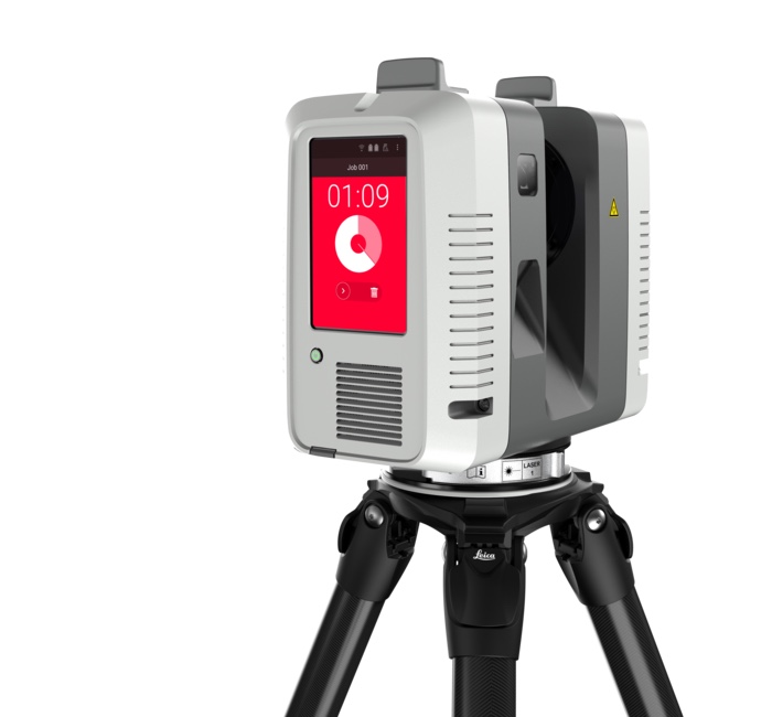
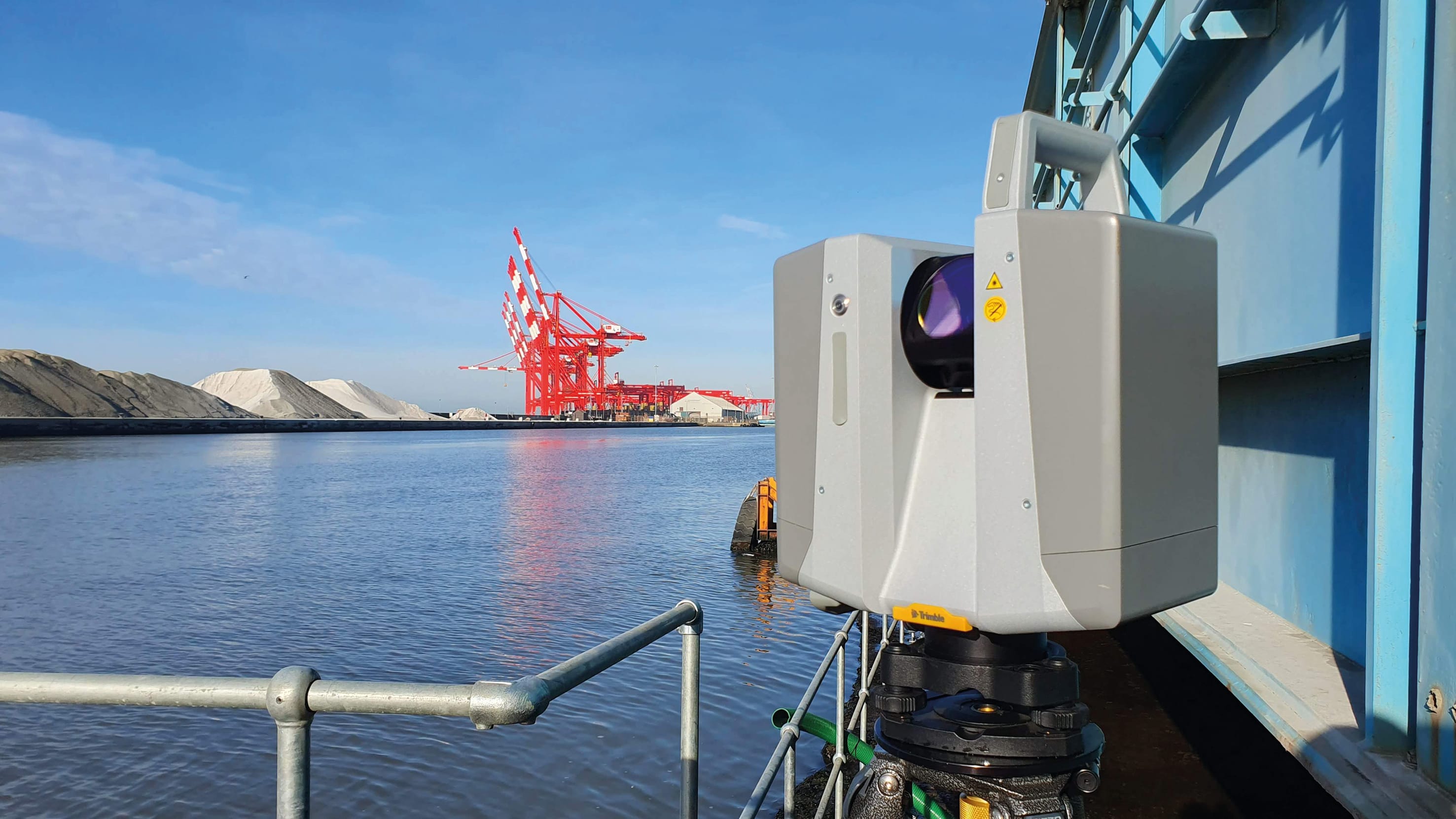
Need help defining the scope for your next scanning project? Get a quote from THE FUTURE 3D, or use our quote request form to build a customized scope of work. Learn more about our 3D laser scanning services and how we deliver accurate, production-ready scan data using equipment like the Leica RTC360 and Trimble X12.
Ready to Start Your Project?
Get a free quote and consultation from our 3D scanning experts.
Get Your Free Quote