The Scan-to-BIM workflow has become the standard method for documenting existing buildings and converting real-world conditions into intelligent digital models. If you are planning a renovation, retrofit, or facility management upgrade, understanding each step of this pipeline is essential for setting realistic expectations on timelines, costs, and deliverables.
This guide walks through the entire Scan-to-BIM process — from the moment a laser scanner captures its first point to the final quality-checked Revit model — so you can make informed decisions about your next project.
What Is Scan-to-BIM?
Scan-to-BIM is the process of capturing a physical space with 3D laser scanning technology and converting that raw scan data into an intelligent Building Information Model (BIM). The term describes an end-to-end workflow involving multiple phases, different teams, and distinct software tools.
The key thing to understand: Scan-to-BIM is not a single automated step. It involves skilled human work at every stage, from planning the scan to modeling the final BIM elements. While AI-assisted tools are accelerating parts of the process, the conversion from raw point cloud data to parametric BIM objects still requires experienced professionals who understand both scanning technology and building construction.
The Five Stages of the Scan-to-BIM Pipeline
Stage 1: Pre-Scan Planning and Site Assessment
Every successful Scan-to-BIM project starts with planning. Before any equipment arrives on site, the scanning team needs to understand the project scope, deliverable requirements, and site conditions.
Key planning activities include:
- Defining the scope — Which areas of the building need to be scanned? Interior only, exterior only, or both? Are mechanical rooms and ceiling plenums included?
- Establishing LOD requirements — What Level of Development does the final BIM model need to achieve? This directly affects both scanning density and modeling effort.
- Identifying access constraints — Are there restricted areas, security requirements, or occupied spaces that limit scanning schedules?
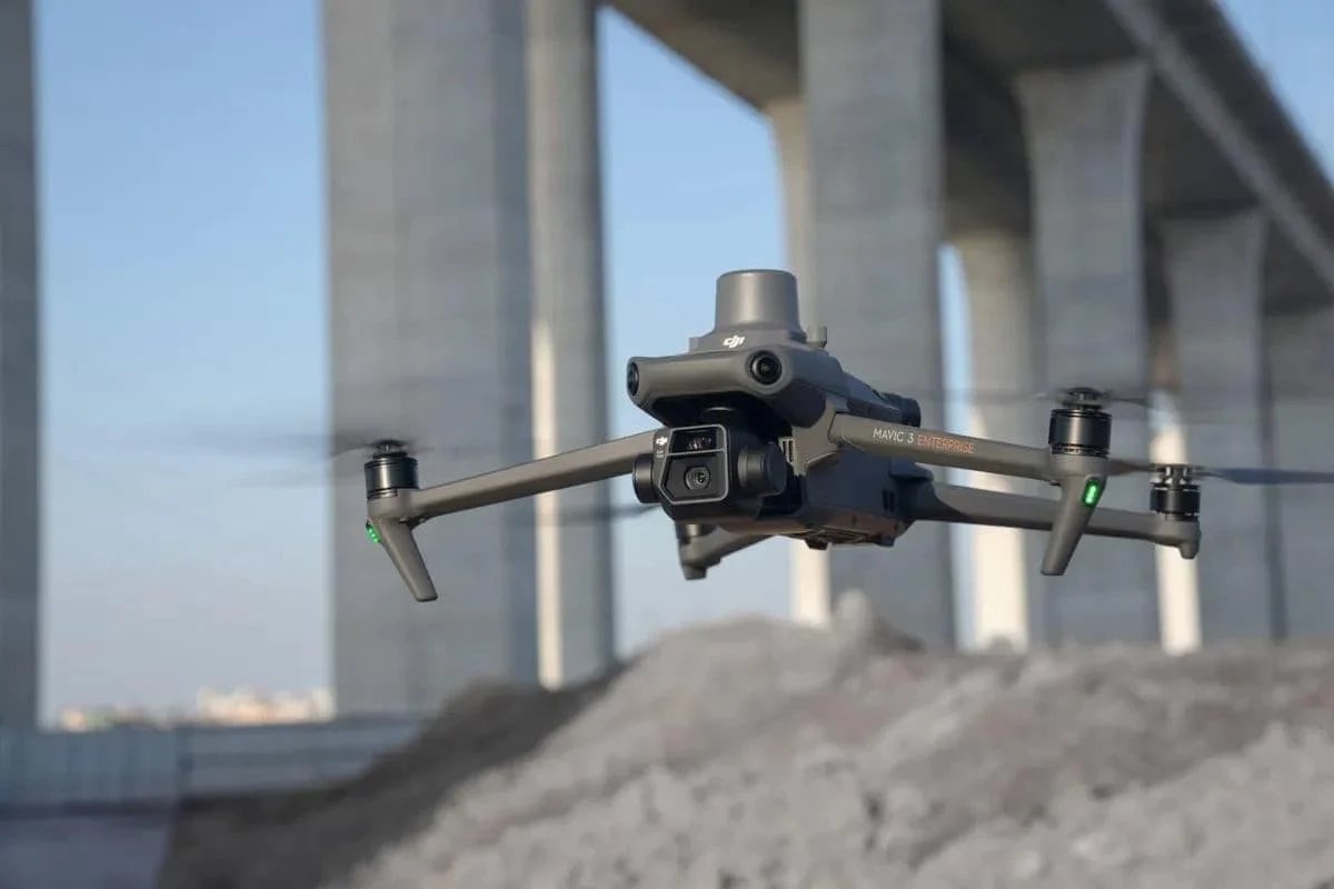
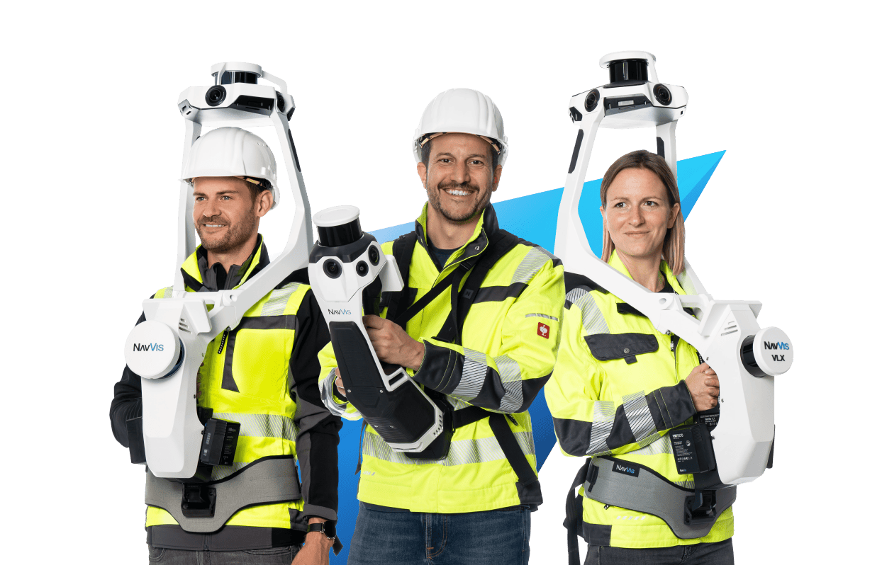
- Selecting equipment — Different scanners suit different environments. A Leica RTC360 excels in commercial interiors, while a NavVis VLX handles large-footprint spaces more efficiently. Drone-mounted LiDAR handles exterior facades and rooftops.
- Setting the coordinate system — Establishing survey control points and a project coordinate system that will carry through from scanning to the final BIM deliverable.
This planning phase typically takes one to three days depending on building complexity, and it directly impacts the quality of everything that follows.
Stage 2: 3D Laser Scanning (Data Capture)
The scanning phase is where the physical building becomes digital data. A field crew sets up terrestrial laser scanners at multiple positions throughout the building, capturing 360-degree point clouds from each setup.
For a typical commercial building, the scanning process involves:
- 50 to 200+ scan positions depending on building size, complexity, and required point density
- Placement of registration targets — Checkerboard or sphere targets placed at strategic locations to help align individual scans
- Scan resolution settings — Higher resolution captures more detail but takes longer per scan position
- Photography — Most modern scanners capture HDR photographs that colorize the point cloud
A scanner like the FARO Focus Premium captures up to 2 million points per second, while the Leica RTC360 captures nearly the same at 2 million points per second with visual inertial system (VIS) technology for automated pre-registration.
For a 50,000 square foot commercial building, scanning typically takes one to three days with a two-person crew. Larger or more complex buildings — hospitals, industrial plants, historic structures — can require a week or more.
Stage 3: Point Cloud Registration and Processing
After field scanning is complete, the individual scan positions must be aligned into a single, unified point cloud. This process is called registration, and it is one of the most critical quality steps in the entire pipeline.
Registration methods include:
- Target-based registration — Using the physical targets placed during scanning to align overlapping scans. Achieves the highest accuracy, typically within 1-2mm.
- Cloud-to-cloud registration — Algorithms like ICP (Iterative Closest Point) match overlapping geometry between adjacent scans. Used when targets are not practical.
- SLAM-based registration — Simultaneous Localization and Mapping technology, common with mobile scanners like the NavVis VLX, provides real-time alignment during capture.
After registration, the unified point cloud goes through cleaning and optimization:
- Noise removal — Eliminating stray points caused by reflective surfaces, glass, dust, or moving objects
- Outlier filtering — Removing points that fall outside expected ranges
- Decimation — Reducing point density in areas where ultra-high resolution is unnecessary, to manage file sizes
- Colorization — Applying photographic color data to each point for visual context
- Coordinate system assignment — Geo-referencing the point cloud to the project coordinate system
Software used for this stage includes Leica Cyclone, FARO SCENE, Autodesk ReCap, and Trimble RealWorks. Processing time varies from hours for a small project to several days for large, complex buildings.
For a deeper look at processing techniques, see our guide on point cloud processing.
Stage 4: Scan Data Delivery
This is the stage where the processed, registered, and cleaned point cloud is delivered to the client in industry-standard formats.
Common delivery formats include:
| Format | Software Compatibility | Typical Use Case |
|---|---|---|
| E57 | Universal — CloudCompare, Cyclone, ReCap, SCENE | Open standard for cross-platform sharing |
| RCP/RCS | Autodesk Revit, AutoCAD, Navisworks | Direct import into Autodesk BIM workflows |
| LAS/LAZ | ArcGIS, QGIS, surveying software | Geospatial and surveying applications |
| OBJ | Various 3D modeling platforms | Mesh-based visualization |
Important note about THE FUTURE 3D’s role: We specialize in Stages 1 through 4 — scanning, registration, processing, and delivery of BIM-conversion-ready 3D laser scan data. Our deliverables are optimized for direct import into Revit and other BIM platforms. The BIM modeling itself (Stage 5) is performed by the client’s in-house team or a specialized third-party BIM firm. This separation allows each specialist to focus on what they do best: we deliver the most accurate scan data possible, and your BIM team builds the intelligent model on top of it.
To learn more about file format differences, see our comparison of E57 vs LAS formats.
Stage 5: BIM Modeling (Scan-to-BIM Conversion)
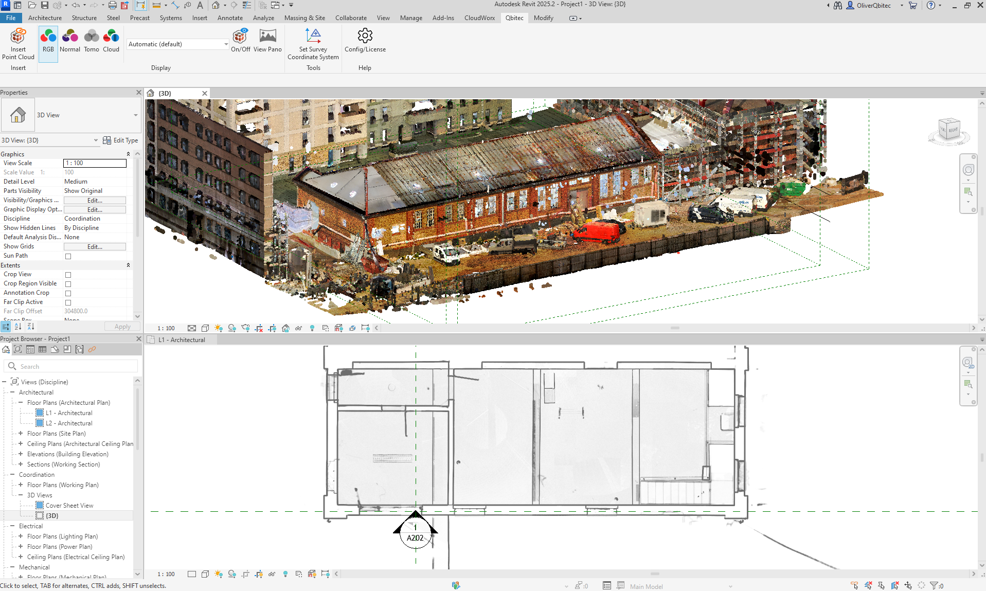
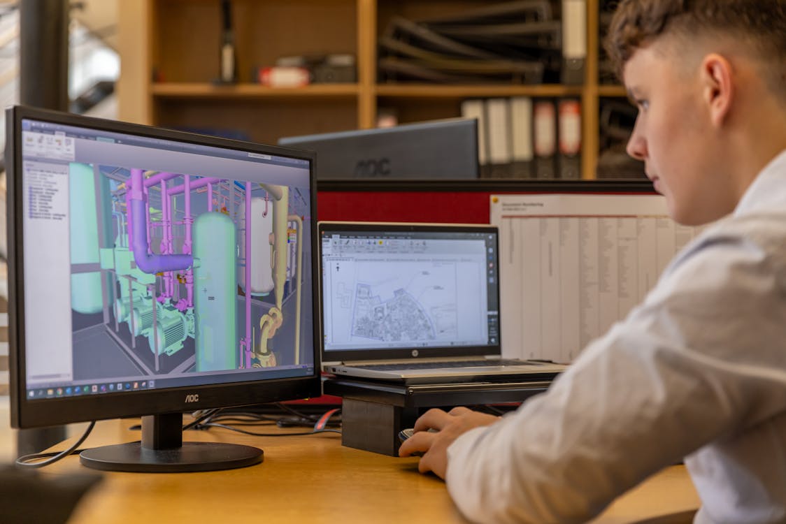
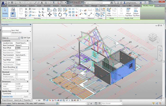
A BIM modeler imports the delivered point cloud into Revit (or another BIM platform like ArchiCAD or Bentley MicroStation) and begins tracing over the scanned geometry to create intelligent parametric objects.
This is the most labor-intensive stage of the pipeline, and the one that requires the deepest construction knowledge. The modeler must:
- Identify building elements — Distinguish walls from partitions, structural columns from architectural columns, supply ducts from return ducts
- Create parametric families — Build or select Revit families that match the scanned geometry
- Assign properties — Add material types, fire ratings, system classifications, and other metadata
- Establish relationships — Connect walls to floors, ducts to air handling units, pipes to fixtures
- Model to specification — Match the agreed-upon LOD level
Understanding LOD Levels
The Level of Development (LOD) specification determines how detailed and information-rich the final BIM model will be. LOD directly impacts both the time and cost of the modeling phase.
| LOD Level | Description | Accuracy | Typical Use Case | Timeline (50K sq ft) | Cost per sq ft |
|---|---|---|---|---|---|
| LOD 200 | Approximate geometry, generic placeholders | Plus or minus 6-12 inches | Conceptual planning, feasibility studies | 2-4 weeks | $0.50-$1.50 |
| LOD 300 | Accurate geometry, specific systems identified | Plus or minus 3-6 inches | Design development, coordination | 4-8 weeks | $1.50-$3.50 |
| LOD 350 | Coordination-ready with connections and interfaces | Plus or minus 2-4 inches | Clash detection, MEP coordination | 6-10 weeks | $2.50-$5.00 |
| LOD 400 | Fabrication-ready with manufacturer-specific detail | Plus or minus 1-3 inches | Construction documentation, shop drawings | 8-16 weeks | $3.50-$7.00+ |
Most renovation and retrofit projects specify LOD 300 as the baseline, with LOD 350 for MEP-heavy areas where clash detection is critical. LOD 400 is typically reserved for fabrication-driven projects.
For a detailed breakdown of what scanning and BIM conversion costs, see our Scan-to-BIM service page and our 3D scanning cost guide.
Quality Assurance: Closing the Loop
The final step in every Scan-to-BIM project is quality assurance — overlaying the completed BIM model against the original point cloud to verify accuracy.
QA checks include:
- Geometric deviation analysis — Measuring the distance between modeled surfaces and the corresponding point cloud data. Deviations exceeding the LOD specification trigger corrections.
- Completeness verification — Confirming that all specified building elements have been modeled
- System classification review — Ensuring MEP systems are correctly categorized and connected
- Clash detection — Running interference checks to identify conflicts between modeled systems
- Report generation — Documenting any deviations, assumptions, or areas where the point cloud data was ambiguous
This QA step is where the truth of the scan data validates the intelligence of the BIM model. Without it, modeling errors can propagate into design decisions, construction documents, and ultimately the built environment.
Software Tools Across the Pipeline
Different software tools serve different stages of the Scan-to-BIM workflow:
| Stage | Software | Purpose |
|---|---|---|
| Scanning | FARO SCENE, Leica Cyclone FIELD | Field data capture and on-site registration |
| Registration | Leica Cyclone, FARO SCENE, Trimble RealWorks | Aligning individual scans into unified point cloud |
| Processing | CloudCompare, Autodesk ReCap, Cyclone | Cleaning, filtering, decimation, coordinate assignment |
| BIM Modeling | Autodesk Revit, ArchiCAD, Bentley MicroStation | Creating intelligent parametric models from point cloud |
| QA/Coordination | Autodesk Navisworks, Solibri, BIMcollab | Clash detection, model review, deviation analysis |
For a broader look at available software, read our guide on the best point cloud software.
Timeline and Cost Expectations
For a standard 50,000 square foot commercial building, here is what a realistic Scan-to-BIM timeline looks like:
| Phase | Duration | Responsible Party |
|---|---|---|
| Pre-scan planning | 1-3 days | Scanning provider (THE FUTURE 3D) |
| 3D laser scanning | 1-3 days | Scanning provider |
| Registration and processing | 2-5 days | Scanning provider |
| Scan data delivery | Same day | Scanning provider |
| BIM modeling (LOD 300) | 4-8 weeks | Client team or BIM firm |
| Quality assurance | 3-5 days | BIM firm with scan data reference |
Total project timeline: 6 to 12 weeks from scanning to final BIM model, depending on building complexity and LOD requirements.
Total cost range:
- Scanning and data delivery: $8,000-$25,000 (varies by building size and complexity)
- BIM modeling at LOD 300: $75,000-$175,000 (varies by modeler rates and building complexity)
- BIM modeling at LOD 200: $25,000-$75,000
These ranges reflect typical U.S. market pricing. For a more detailed breakdown, see our BIM scanning guide.
How THE FUTURE 3D Fits Into Your Scan-to-BIM Workflow
THE FUTURE 3D provides the scanning foundation that makes accurate BIM modeling possible. We deliver BIM-conversion-ready 3D laser scan data in E57, RCP, LAS, and OBJ formats, captured with professional-grade equipment including Leica RTC360, FARO Focus Premium, and NavVis VLX scanners.
Our scan data is optimized for direct import into Revit and other BIM platforms, giving your modeling team or external BIM firm a precise, reliable foundation for their work. Whether your BIM team is in-house or you work with a third-party modeling firm, our deliverables integrate seamlessly into the Scan-to-BIM workflow.
Frequently Asked Questions
How long does the scanning portion of a Scan-to-BIM project take?
For a typical commercial building of 20,000-50,000 square feet, the on-site scanning takes one to three days. Processing and registration add another two to five days. The BIM modeling phase — handled separately by a modeling team — takes four to sixteen weeks depending on LOD requirements.
Can a point cloud be automatically converted to a BIM model?
Not with current technology. While AI-assisted tools can detect planes and basic geometry, converting a point cloud into a fully intelligent BIM model with correct system classifications, material properties, and object relationships requires skilled human modeling. This is expected to improve over the coming years, but manual BIM expertise remains essential.
What is the difference between LOD 200 and LOD 300?
LOD 200 provides approximate geometry with generic placeholders — useful for conceptual planning. LOD 300 provides accurate geometry with specific systems identified — suitable for design development and coordination. The cost and time difference is significant: LOD 300 typically costs two to three times more than LOD 200.
Does THE FUTURE 3D create Revit models?
No. THE FUTURE 3D specializes in delivering BIM-conversion-ready 3D laser scan data. We capture, process, and deliver point cloud data in industry-standard formats that your BIM team or a specialized modeling firm can import directly into Revit. This approach ensures you get the highest quality scan data from dedicated scanning specialists, while your modeling team focuses on BIM expertise.
What file format should I request for Revit import?
For Revit workflows, request RCP/RCS format — these are Autodesk’s native point cloud formats optimized for Revit performance. We also deliver E57 as a universal backup format that works across all major platforms. Learn more about point cloud file formats.
Ready to start a Scan-to-BIM project? Get a quote from THE FUTURE 3D or explore our Scan-to-BIM service to learn how our scan data powers accurate BIM modeling. For a look at where the industry is heading, see our assessment of whether AI can convert point clouds to BIM in 2026.
Ready to Start Your Project?
Get a free quote and consultation from our 3D scanning experts.
Get Your Free Quote