Point cloud processing is the critical bridge between raw 3D scan data and a usable deliverable. When a laser scanner captures a building, the output is millions — sometimes billions — of individual measured points. Before that data can be used for BIM modeling, construction verification, or facility management, it needs to go through a structured processing pipeline that transforms it from a collection of raw measurements into a clean, registered, and properly formatted dataset.
This guide covers every step of point cloud processing, the software tools professionals rely on, and the best practices that separate production-quality data from unusable noise.
What Is Point Cloud Processing?
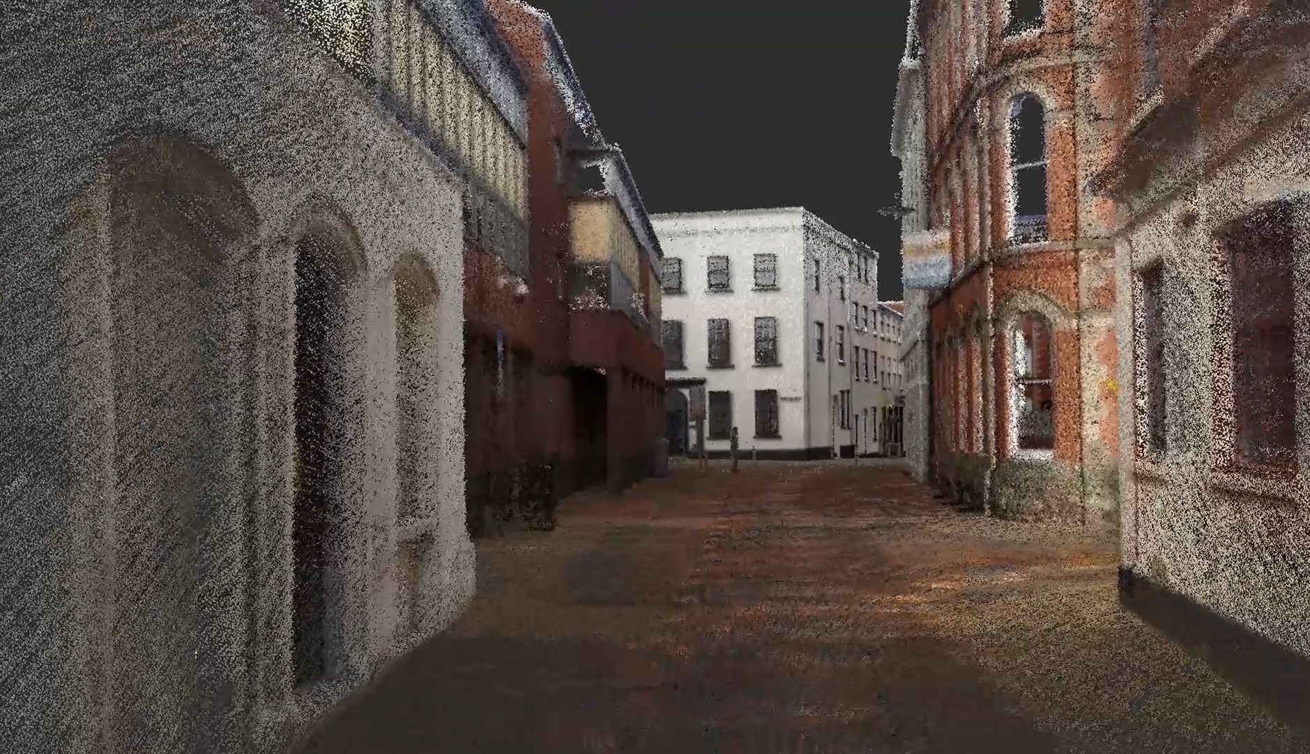
Point cloud processing is the series of steps that transform raw scan data into a clean, aligned, and deliverable dataset. It includes everything from aligning individual scan positions (registration) to removing unwanted points (cleaning), reducing file sizes (decimation), and exporting in the correct format for downstream workflows.
Think of it as the post-production phase of a 3D laser scanning project. The scanning crew captures the raw data in the field; the processing team refines that data into a finished product.
The processing workflow follows a consistent sequence regardless of the project type:
- Registration — Aligning individual scans into one unified point cloud
- Cleaning — Removing noise, outliers, and unwanted objects
- Decimation — Reducing point density to manage file sizes
- Colorization — Applying photographic color to each point
- Coordinate system assignment — Geo-referencing and setting the project datum
- Quality checks — Verifying accuracy and completeness
- Export — Delivering in the required file formats
Step 1: Registration — Aligning Individual Scans
Registration is the process of aligning multiple scan positions into a single, cohesive point cloud. A typical building scan involves dozens to hundreds of individual scan setups, each capturing a 360-degree snapshot from its location. These overlapping snapshots must be precisely stitched together.
Target-Based Registration
Target-based registration uses physical reference objects — checkerboard targets, spheres, or special reflective stickers — placed throughout the scan area before capture begins. The software identifies these targets in overlapping scans and uses their known positions to calculate the transformation that aligns each scan to a common coordinate system.
Advantages:
- Highest achievable accuracy (typically 1-2mm between scan pairs)
- Deterministic — results are consistent and repeatable
- Works well in feature-poor environments (blank walls, open spaces)
Disadvantages:
- Requires pre-placement of targets before scanning
- Adds setup time in the field
- Targets can be accidentally moved or obscured
Cloud-to-Cloud Registration
Cloud-to-cloud (also called targetless or surface-matching) registration uses algorithms to match overlapping geometry between adjacent scans without physical targets. The most common algorithm is ICP (Iterative Closest Point), which iteratively refines the alignment by minimizing the distance between corresponding points in overlapping regions.
Advantages:
- No targets needed — faster field work
- Works with natural building features
- Can be applied retroactively to existing scan data
Disadvantages:
- Requires sufficient geometric overlap (30%+ recommended)
- Less reliable in repetitive environments (corridors with identical geometry)
- Accuracy depends on surface features and scan quality
SLAM-Based Registration
SLAM (Simultaneous Localization and Mapping) registration is used primarily with mobile scanning platforms like the NavVis VLX or handheld scanners. SLAM algorithms build a map of the environment in real-time as the scanner moves through a space, continuously tracking position and orientation.
Advantages:
- Real-time alignment during capture — no post-processing registration needed
- Extremely fast data capture for large-footprint spaces
- Works well in complex, multi-room environments
Disadvantages:
- Lower absolute accuracy than target-based methods (typically 5-15mm)
- Drift can accumulate over long traverse distances
- Requires loop closure for best results
Most professional projects use a combination of these methods. Target-based for the highest-priority control points, cloud-to-cloud for filling in gaps, and SLAM for mobile scanning segments.
Step 2: Cleaning — Removing Unwanted Data
Raw point clouds contain more than just the building surfaces you want to document. They also capture anything that was visible during scanning — people walking through, temporary construction equipment, vehicles, vegetation, reflections, and atmospheric particles.
Noise Removal
Noise points are stray measurements that do not represent real surfaces. They are caused by:
- Multi-path reflections from glass, mirrors, and polished surfaces
- Edge artifacts where the laser beam hits the edge of an object and splits between the foreground and background
- Atmospheric interference from dust, rain, or fog
- Moving objects that create smeared or duplicated geometry
The standard approach to noise removal is Statistical Outlier Removal (SOR), which analyzes each point’s relationship to its neighbors. Points that are statistically distant from their local neighborhood (typically using 6 to 12 neighbors) are classified as noise and removed.
Manual Cleaning
Some unwanted objects cannot be removed algorithmically. People, vehicles, temporary scaffolding, and construction equipment often need to be manually selected and deleted. Most professional software tools provide clipping boxes, polygonal selection tools, and classification filters for this purpose.
Point Classification
For projects involving exterior scanning — particularly topographic surveys — point classification becomes important. Points are categorized into classes such as:
- Ground
- Building
- Vegetation (low, medium, high)
- Water
- Noise
- Unclassified
The ASPRS LAS specification defines standard classification codes that most software tools support. Automated classification algorithms handle the bulk of this work, with manual review for accuracy.
Step 3: Decimation — Managing File Sizes
A single scan position can produce 20 to 100 million points. A full building scan with 100+ positions can easily exceed a billion points. At this density, file sizes reach 10-50 GB or more, which creates practical challenges for storage, transfer, and downstream software performance.
Decimation reduces point density while preserving the essential geometry of the scanned surfaces. Common approaches include:
- Spatial sampling — Keeping only one point within each defined voxel (3D grid cell). A 5mm voxel size, for example, retains no more than one point per 5mm cube.
- Random subsampling — Retaining a random percentage of total points. Simple but less controlled than spatial sampling.
- Octree-based decimation — Adaptively varying point density based on surface complexity. Flat walls get fewer points; detailed areas retain more.
The appropriate decimation level depends on the project’s downstream use. BIM modeling typically works well with 5-10mm point spacing. Construction verification may need 2-5mm. Heritage documentation often requires the full captured density.
Step 4: Colorization and Enhancement
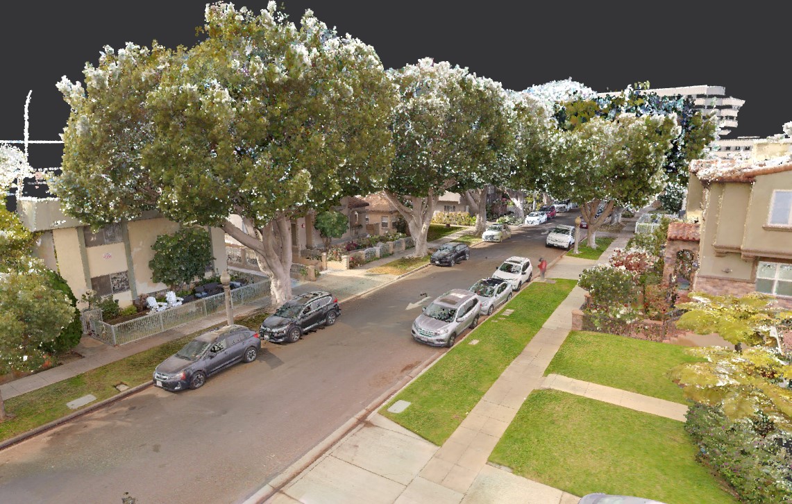
Modern laser scanners capture HDR photographs alongside the geometric scan data. During processing, these photographs are projected onto the point cloud, assigning RGB color values to each point. The result is a photorealistic colored point cloud that provides visual context alongside precise measurement data.
Additional enhancement steps can include:
- Intensity normalization — Standardizing the laser reflectance intensity values across different scan positions
- True color calibration — Adjusting color balance for consistent appearance across different lighting conditions
- HDR blending — Combining multiple exposure levels for optimal visual quality in both bright and dark areas
Step 5: Coordinate Systems and Geo-Referencing
Every point cloud needs to exist within a defined coordinate system. The choice of coordinate system depends on the project type and downstream use:
- Local coordinates — An arbitrary coordinate system defined by the project. Common for interior building scans where the coordinate origin is set at a specific building corner or column grid intersection.
- State Plane / UTM — Standard geographic coordinate systems used for surveying and mapping projects. Required when the point cloud needs to align with GIS data, property boundaries, or civil engineering designs.
- Building grid coordinates — Aligned to the building’s structural grid, matching existing architectural drawings.
Geo-referencing connects the point cloud to a real-world coordinate system using survey control points. These are typically established by a licensed surveyor using GPS/GNSS equipment or total station measurements.
Software Comparison
The choice of processing software depends on the project type, hardware capabilities, and downstream workflow requirements.
| Software | License | Strengths | Best For |
|---|---|---|---|
| Leica Cyclone | Commercial ($10K+) | Industry standard, handles massive datasets, advanced registration | Professional survey-grade projects |
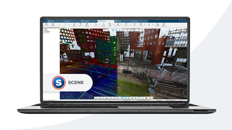
| FARO SCENE | Commercial ($5K+) | Tight integration with FARO scanners, automated workflows | FARO-ecosystem projects |
| Autodesk ReCap | Subscription (~$400/yr) | Revit/AutoCAD integration, accessible interface | Autodesk BIM workflows |
| CloudCompare | Free / Open Source | Powerful analysis, plugin ecosystem, cross-platform | Research, analysis, budget projects |
| Trimble RealWorks | Commercial ($8K+) | Strong survey workflows, coordinate system management | Surveying firms |
When to Use Each Tool
Leica Cyclone is the go-to choice for professional scanning firms handling large, multi-site projects. It handles billion-point datasets without compromising on registration accuracy or processing speed.
FARO SCENE is optimized for FARO scanner output and provides a streamlined processing pipeline for firms that standardize on FARO equipment.
Autodesk ReCap is the natural choice when the point cloud is destined for Revit or AutoCAD. Its RCP/RCS output format loads directly into Autodesk products with optimized performance.
CloudCompare fills an essential role as a free, open-source platform for analysis, comparison, and custom processing workflows. Its plugin architecture supports advanced operations like change detection, surface deviation analysis, and custom scripting.
Trimble RealWorks serves surveying firms that need tight integration with survey control, coordinate transformations, and deliverables formatted for civil engineering workflows.
Best Practices for Point Cloud Processing
1. Establish Quality Thresholds Before Processing
Define acceptable registration accuracy, point density, and noise levels before you start processing. For BIM-targeted projects, registration accuracy should be within 3mm between scan pairs, with overall point cloud accuracy within 5mm of survey control.
2. Process in Stages, Not All at Once
Break large projects into processing zones (floors, wings, or functional areas) and process each zone independently before combining them. This approach is easier to manage, easier to QA, and easier to troubleshoot when issues arise.
3. Preserve the Original Data
Never modify the original scan files. Always work on copies. If a processing step introduces errors, you need the ability to return to the source data.
4. Document Your Processing Decisions
Record the registration method used, the cleaning operations performed, decimation parameters, and coordinate system settings. This metadata is essential for downstream users who need to understand the data’s provenance and limitations.
5. Validate Against Independent Measurements
Compare processed point cloud measurements against independently measured survey control points. This provides an objective check on overall accuracy that goes beyond the registration software’s self-reported statistics.
6. Optimize for the Downstream Workflow
A point cloud destined for BIM modeling has different optimization needs than one for construction verification or heritage documentation. Tailor your decimation level, file format, and coordinate system to the specific end use.
Common Processing Challenges
| Challenge | Cause | Solution |
|---|---|---|
| Poor registration accuracy | Insufficient overlap between scans | Rescan with additional positions; use targets in problem areas |
| Excessive noise | Reflective surfaces (glass, metal) | Apply SOR filtering; manually clean problem areas |
| Large file sizes | Over-dense scanning resolution | Apply voxel-based decimation appropriate for use case |
| Color inconsistency | Varying lighting across scan positions | Apply intensity normalization and color calibration |
| Coordinate drift | Long SLAM traverses without loop closure | Add loop closures; tie to survey control at intervals |
How THE FUTURE 3D Handles Point Cloud Processing
THE FUTURE 3D processes all scan data in-house using professional-grade software and established QA workflows. Our deliverables are registered, cleaned, colorized, and formatted specifically for your project’s downstream needs — whether that is BIM modeling in Revit, construction verification, or facility management.
We deliver point cloud data in E57, RCP, LAS, and OBJ formats, with registration accuracy reports and processing documentation included. For projects feeding into a Scan-to-BIM workflow, our data is optimized for direct import into Revit with minimal additional preparation needed by the modeling team.
Learn more about our 3D laser scanning services or explore what a point cloud is for foundational context.
Frequently Asked Questions
How long does point cloud processing take?
Processing time depends on dataset size and project complexity. A small interior project (20-30 scan positions) might take a few hours. A large commercial building (200+ positions) can take two to five days. Processing includes registration, cleaning, colorization, and format export.
Can I process point clouds on a standard office computer?
Basic processing with small datasets is possible on modern workstations with 32GB+ RAM and a dedicated GPU. Large datasets (500M+ points) require workstations with 64-128GB RAM, fast SSD storage, and modern GPUs. CloudCompare runs on standard hardware for analysis tasks, while Cyclone and ReCap benefit significantly from high-end specifications.
What is the difference between E57 and RCP formats?
E57 is an open standard format compatible with virtually all point cloud software. RCP/RCS are Autodesk’s proprietary formats optimized for performance in Revit and AutoCAD. For Autodesk workflows, RCP is preferred. For cross-platform sharing, E57 is the standard choice. See our detailed E57 vs LAS comparison and our point cloud file formats guide.
How much does point cloud processing software cost?
Costs range from free (CloudCompare) to $400/year (Autodesk ReCap subscription) to $5,000-$15,000+ for professional packages like Leica Cyclone, FARO SCENE, or Trimble RealWorks. The right choice depends on your project volume, scanner ecosystem, and downstream deliverable requirements.
What registration accuracy should I expect?
Target-based registration typically achieves 1-2mm accuracy between adjacent scan pairs. Cloud-to-cloud registration achieves 2-5mm. SLAM-based systems achieve 5-15mm depending on traverse length and loop closure quality. Overall point cloud accuracy relative to survey control is typically within 3-6mm for professional-grade projects.
Need production-ready point cloud data for your project? Get a quote from THE FUTURE 3D or explore our 3D laser scanning services to learn how we deliver processed, registered scan data ready for your workflow.
Ready to Start Your Project?
Get a free quote and consultation from our 3D scanning experts.
Get Your Free Quote