SLAM scanning has become one of the most important technologies in the 3D scanning industry over the past decade. It is the technology that allows a person to walk through a building with a scanner and produce a complete 3D point cloud of the environment — something that was impossible before SLAM algorithms matured.
But SLAM is not a single technology. It is a family of algorithms and sensor configurations that solve the same fundamental problem: how does a scanner determine where it is while simultaneously building a map of its surroundings? Understanding how SLAM works, where it excels, and where it falls short helps AEC professionals, facility managers, and project planners choose the right scanning approach for their specific needs.
What SLAM Stands For
SLAM stands for Simultaneous Localization and Mapping. The name describes exactly what the technology does:
- Simultaneous: Both tasks happen at the same time, in real time
- Localization: The scanner determines its own position and orientation in space
- And
- Mapping: The scanner builds a map (point cloud) of the surrounding environment
The core challenge is that these two tasks are interdependent. To build an accurate map, you need to know where the scanner is. To know where the scanner is, you need an accurate map. SLAM algorithms solve this chicken-and-egg problem through continuous estimation, correction, and refinement.
How SLAM Algorithms Work
A SLAM scanner contains multiple sensors that work together to solve the localization and mapping problem. Here is how each contributes.
LiDAR Sensor
The LiDAR sensor is the primary mapping tool. It fires rapid laser pulses at surrounding surfaces and measures the distance to each point based on the pulse return time. In mobile SLAM scanners, the LiDAR sensor captures measurements continuously as the operator moves through the space.
The LiDAR data provides the geometric information — where walls, floors, ceilings, equipment, and other surfaces are located relative to the scanner at each moment. Modern SLAM scanners capture hundreds of thousands to millions of points per second.
Inertial Measurement Unit (IMU)
The IMU is an internal sensor that measures acceleration and rotational velocity. It tracks the scanner’s motion between LiDAR frames — detecting turns, tilts, speed changes, and vibrations. This motion data fills the gaps between LiDAR measurements, helping the SLAM algorithm maintain position tracking during transitions.
The IMU provides short-term motion data that is highly precise over brief intervals but accumulates drift over time. Left uncorrected, IMU drift would cause the scanner’s estimated position to diverge from its actual position. SLAM algorithms use LiDAR data to continuously correct this drift.
Cameras (Optional but Common)
Many SLAM scanners include cameras that capture visual imagery alongside the LiDAR data. Cameras serve multiple purposes:
- Visual odometry: Camera images provide additional feature matching data for the SLAM algorithm, improving localization accuracy
- Colorization: RGB imagery is mapped onto point cloud data for photorealistic visualization
- Panoramic documentation: Full 360-degree imagery enables virtual walkthrough experiences
The SLAM Algorithm Pipeline
Here is how these sensors work together in a typical SLAM processing pipeline:
1. Scan matching. As new LiDAR data arrives, the algorithm compares it against the most recent portion of the map. By finding the best alignment between new measurements and existing data, it estimates how much the scanner has moved since the last frame.
2. IMU integration. Between LiDAR frames, the IMU provides motion estimates. The algorithm fuses the IMU data with the scan matching results to produce a continuous position estimate that is more accurate than either source alone.
3. Map building. Each new set of LiDAR measurements is added to the growing map at the estimated position. The map expands incrementally as the operator walks through the space.
4. Loop closure. When the operator returns to a previously scanned area, the algorithm detects the overlap. It then calculates the accumulated drift (the difference between where the algorithm thinks the scanner is and where the map says it should be) and distributes a correction across the entire walk path. This is the single most important step for maintaining accuracy across large areas.
5. Global optimization. After the scan is complete, a final optimization pass refines the entire map, adjusting all positions simultaneously to minimize overall error. This produces the final, cleaned point cloud.
Types of SLAM
SLAM is not a single algorithm but a broad family of approaches. The two most relevant categories for 3D scanning are 2D SLAM and 3D SLAM.
2D SLAM
2D SLAM operates on a single horizontal plane. The scanner captures a cross-section of the environment — walls, obstacles, and openings at a single height — and builds a 2D floor plan map. This is the technology used in robotic vacuum cleaners and many autonomous mobile robots.
For 3D scanning purposes, some mobile scanners use a 2D LiDAR sensor mounted on a rotating platform. As the platform rotates, the 2D scanner sweeps through 3D space, effectively creating 3D coverage from a 2D sensor. This approach (used in earlier GeoSLAM products) trades some point density for mechanical simplicity.
3D SLAM
3D SLAM operates in full three-dimensional space. The scanner captures surfaces at all angles simultaneously using multi-layer LiDAR sensors that measure in multiple planes at once. The SLAM algorithm works in 6 degrees of freedom (X, Y, Z position + roll, pitch, yaw orientation).
Modern professional SLAM scanners (NavVis VLX 3, NavVis MLX) use native 3D LiDAR sensors, providing denser point clouds and more robust localization than 2D-to-3D approaches.
Visual SLAM
Visual SLAM (V-SLAM) uses cameras instead of — or in addition to — LiDAR as the primary sensing modality. The algorithm extracts visual features (corners, edges, textures) from camera images and tracks how those features move between frames to estimate the camera’s motion.
Visual SLAM is common in augmented reality applications (smartphone AR, mixed reality headsets) and some consumer scanning products. For professional AEC applications, LiDAR-based SLAM is preferred because it provides direct distance measurements that are independent of lighting conditions and surface textures.
SLAM Accuracy: What Determines It
SLAM accuracy is not a fixed specification — it varies based on the scanner, the environment, and the operator’s technique. Understanding the factors that affect accuracy helps project planners set realistic expectations.
Scanner Hardware
Higher-quality LiDAR sensors, better IMU components, and more capable processing hardware all contribute to better SLAM accuracy. Professional systems like the NavVis VLX 3 achieve ±5mm absolute accuracy with dual 32-layer LiDAR and precision IMU components. Consumer-grade or lower-end systems may achieve 10-30mm accuracy.
Environmental Geometry
SLAM algorithms need geometric features to localize against. The accuracy of the result depends heavily on the richness of features in the environment.
High-accuracy environments:
- Furnished offices (desks, chairs, bookshelves, partitions)
- Industrial facilities (equipment, piping, racking)
- Complex architecture (columns, alcoves, stairwells, irregular layouts)
Lower-accuracy environments:
- Long, featureless corridors
- Empty parking garages
- Large open spaces with minimal interior structure
- Symmetric spaces where different locations look identical to the scanner
Walk Path Planning
How the operator moves through the space directly affects SLAM accuracy. Key practices:
- Steady pace: Walking at a consistent 3-5 km/h provides optimal data quality. Running or erratic movements degrade IMU integration.
- Loop closures: Returning to previously scanned areas allows the algorithm to detect and correct drift. Without loop closures, accuracy degrades over long walk distances.
- Overlap: Scanning from multiple angles (walking an area in different directions) provides redundant data that strengthens the map.
- Avoiding featureless stretches: Long walks through empty corridors without returning to feature-rich areas allow drift to accumulate uncorrected.
Scan Duration and Area
SLAM accuracy tends to degrade slightly over very long scan sessions because IMU drift accumulates between loop closures. For very large facilities (500,000+ square feet), professional operators break the scan into multiple sessions with shared overlap zones, then register the sessions together during processing.
Key SLAM Scanners on the Market
Several manufacturers produce professional SLAM scanners for the AEC market. Here are the most widely deployed systems.
NavVis VLX 3
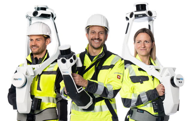
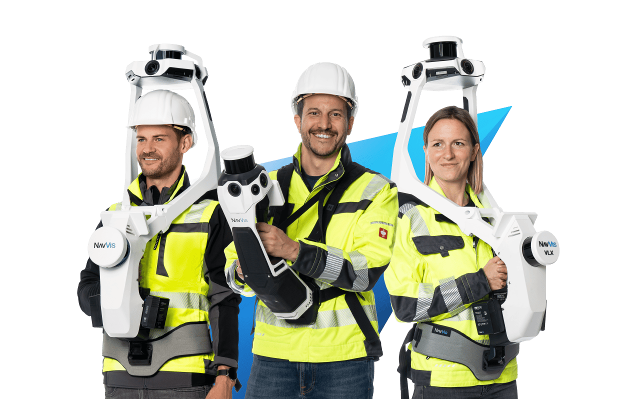
The NavVis VLX 3 is a wearable mobile mapping system built for high-volume production scanning. Its dual 32-layer LiDAR sensors capture 2.56 million points per second at ±5mm accuracy. The integrated four-camera panoramic system captures imagery for colorized point clouds and virtual walkthroughs via NavVis IVION.
| Specification | Value |
|---|---|
| Form factor | Wearable vest |
| LiDAR | 2 x 32-layer, 2.56M pts/sec |
| Accuracy | ±5mm absolute, ±3mm relative |
| Weight | 8.5 kg |
| Battery | Up to 1.5 hours |
| Coverage | 200,000-300,000 sqft/day |
Best suited for: Large-area professional scanning — offices, hospitals, warehouses, campuses, industrial facilities.
NavVis MLX
The NavVis MLX is a trolley-mounted mobile mapping system designed for flat, accessible environments. It uses a single LiDAR sensor at 640,000 points per second and weighs 3.6 kg.
| Specification | Value |
|---|---|
| Form factor | Wheeled trolley |
| LiDAR | Single sensor, 640K pts/sec |
| Accuracy | ±5mm absolute, ±3mm relative |
| Weight | 3.6 kg (scanner unit) |
| Terrain | Flat surfaces only |
Best suited for: Large single-floor spaces — warehouses, retail, exhibition halls, parking structures.
GeoSLAM ZEB Series
GeoSLAM produces handheld SLAM scanners designed for rapid documentation tasks. The ZEB Horizon RT captures at 300,000 points per second and weighs approximately 1 kg.
| Specification | Value |
|---|---|
| Form factor | Handheld |
| LiDAR | Single sensor, 300K pts/sec |
| Accuracy | 6-15mm (varies by environment) |
| Weight | ~1 kg |
| Battery | ~3.5 hours |
Best suited for: Quick documentation, confined spaces, mines, caves, and applications where portability is the primary requirement.
Leica BLK2GO
The Leica BLK2GO is a handheld SLAM scanner that captures at 420,000 points per second. It uses a combination of LiDAR and visual SLAM for localization.
| Specification | Value |
|---|---|
| Form factor | Handheld |
| LiDAR | Single sensor, 420K pts/sec |
| Accuracy | 6-15mm |
| Weight | 775 g |
| Battery | ~45 minutes |
Best suited for: Quick interior documentation, real estate scanning, insurance documentation, and light-duty commercial applications.
When SLAM Scanning Is the Right Choice
SLAM scanning excels in specific scenarios where its speed and accessibility advantages outweigh the accuracy tradeoff relative to tripod scanning.
Large-Area Documentation
Any project involving 50,000+ square feet of interior space should evaluate SLAM scanning. The 7-10x speed advantage over tripod scanning translates to days saved in the field and significant cost reduction. Warehouses, hospitals, universities, retail portfolios, and corporate campuses are all ideal SLAM applications.
Occupied Building Scanning
When buildings cannot be vacated for scanning — offices during business hours, hospitals with patients, schools in session — SLAM scanning minimizes disruption. The operator walks through like any other visitor without setting up tripods, marking positions, or asking people to clear areas.
Rapid Condition Assessment
When the goal is a quick spatial inventory rather than precision geometry — documenting room dimensions, ceiling heights, layout configurations — SLAM provides sufficient data at a fraction of the time and cost of tripod scanning.
Facility Management and Space Planning
Ongoing facility management needs do not typically require millimeter accuracy. Space planning, move management, lease administration, and maintenance planning all work effectively with SLAM-grade data (5-15mm accuracy).
Construction Progress Documentation
Regular scanning during construction to document progress benefits from SLAM’s speed. Monthly or bi-weekly scans of an active construction site are practical with SLAM but prohibitively time-consuming with tripod methods.
When Tripod Scanning Is Better
Despite SLAM’s advantages, there are clear scenarios where tripod scanning remains the right tool.
Construction Verification and QA/QC
When point cloud data will be compared against design models to verify construction tolerances, the 1-3mm accuracy of tripod scanning is essential. Structural deviations, slab flatness, and curtain wall alignment all require measurement precision beyond SLAM’s capability.
Mechanical and MEP Documentation
Dense mechanical rooms, process piping, and electrical infrastructure require the highest point density and accuracy to capture small-diameter components. A 10mm SLAM accuracy can mean the difference between correctly identifying a 4” pipe and mistaking it for a 6” pipe.
Small Projects
For projects under about 20,000 square feet, the speed advantage of SLAM is less dramatic (saving hours rather than days), while the accuracy advantage of tripod scanning is always present. The cost difference on small projects is also smaller.
Legal and Regulatory Documentation
When scan data may be used as legal evidence, insurance documentation, or regulatory compliance proof, the documented higher precision of tripod scanning provides stronger evidentiary value.
The Future of SLAM Technology
SLAM technology continues to improve along several fronts.
Hardware Advances
LiDAR sensors are getting denser (more layers, higher point rates), lighter, and more energy-efficient. Each generation of mobile scanner captures more data with less weight and longer battery life.
Algorithm Improvements
SLAM algorithms are incorporating machine learning techniques for better feature detection, more robust loop closure in challenging environments, and faster processing. Real-time SLAM quality is approaching what was only achievable in post-processing a few years ago.
Integration with Other Technologies
SLAM is increasingly combined with other positioning technologies — Ultra-Wideband (UWB) beacons, 5G positioning, and visual localization — to improve accuracy in challenging environments. Facilities that install UWB anchor points can provide SLAM scanners with external reference data that reduces drift.
Outdoor SLAM
Traditional SLAM was developed for indoor environments where geometric features are abundant. Extending SLAM to outdoor and transitional environments (building perimeters, construction sites, mixed indoor/outdoor facilities) is an active area of development. Improved IMU technology and multi-sensor fusion are making outdoor SLAM increasingly viable.
Frequently Asked Questions
Is SLAM scanning accurate enough for architectural documentation?
Yes. SLAM scanning at 5-10mm accuracy is sufficient for as-built architectural documentation, space planning, renovation design, and facility management applications. For BIM modeling at LOD 200 and general LOD 300, SLAM data provides adequate precision. For precision applications (MEP coordination, structural analysis, construction QA/QC), tripod scanning at 1-3mm is recommended.
How does SLAM handle multi-story buildings?
SLAM scanners track position in full 3D space, including vertical movement. The operator walks up stairs, rides elevators, or takes ramps, and the SLAM algorithm tracks the level change. The NavVis VLX 3 (wearable) handles stairs and level changes naturally. The NavVis MLX (trolley) requires flat, accessible floors and cannot navigate stairs.
What happens if SLAM drift is too large?
If drift accumulates beyond acceptable limits — typically due to long stretches without loop closures or featureless environments — the resulting point cloud will show misalignment. Professional operators prevent this through careful walk planning with frequent loop closures. If drift does occur, post-processing software can apply manual corrections, though significant drift may require re-scanning affected areas.
Can SLAM data be combined with tripod scan data?
Yes. Both SLAM and tripod point clouds can be registered into a single coordinate system using shared control points, targets, or cloud-to-cloud alignment. The combined dataset provides SLAM’s coverage speed with tripod precision in critical areas. This hybrid approach is increasingly common for complex projects.
How long does SLAM processing take?
Processing time depends on the scan area and the scanner used. For a 100,000-square-foot building captured with the NavVis VLX 3, initial processing typically takes 2-4 hours. Additional deliverable production (floor plans, format conversion, cleaning) adds 1-3 days. Total project turnaround from field capture to deliverable is typically 3-7 business days.
Does SLAM work in complete darkness?
Yes. SLAM scanners use LiDAR, which generates its own laser light and does not depend on ambient lighting. A SLAM scanner works in complete darkness, underground facilities, and windowless spaces. The cameras (used for colorization and visual SLAM augmentation) do require light, but the core SLAM localization functions are light-independent.
Need SLAM scanning for your project? Get a quote from THE FUTURE 3D. We deploy professional SLAM scanning technology including the NavVis VLX 3 and NavVis MLX for projects of any size. Learn more about how 3D scanning works or compare mobile vs. terrestrial scanning approaches.
Ready to Start Your Project?
Get a free quote and consultation from our 3D scanning experts.
Get Your Free Quote