Sports broadcast production is a logistics problem disguised as a creative one. Before a single frame is captured, production teams must solve a series of spatial challenges: where to position cameras for optimal sightlines, how to route miles of cable through existing infrastructure, where to build temporary broadcast compounds, and how to integrate hundreds of pieces of equipment into a venue that was designed for spectators — not television production.
3D scanning provides the spatial data that transforms these logistics challenges from guesswork into engineering.
The Camera Placement Problem
A major live sports broadcast may use 20-40+ camera positions for a single event. Each position must satisfy simultaneous requirements:
Sightline Requirements
Every camera must have an unobstructed view of its assigned coverage area. This sounds simple, but in practice:
- Structural columns block sightlines at predictable but inconvenient angles
- Scoreboard and lighting infrastructure creates shadows and obstructions
- Spectator seating geometry means that cameras at certain heights cannot see certain parts of the field
- Temporary structures (hospitality platforms, VIP areas) create new obstructions that did not exist in the original venue design
Structural Requirements
Cameras range from 10kg handheld units to 100+ kg robotic camera systems. Each mounting location must:
- Support the camera weight plus operator and equipment
- Provide stable mounting that prevents vibration during use
- Allow the range of motion the camera operator needs (pan, tilt, zoom)
- Comply with venue structural load ratings (particularly for elevated positions)
Cable Access
Every camera connects to the broadcast compound via fiber optic and power cables. Cable routing must:
- Follow paths that do not obstruct spectator egress
- Maintain minimum bend radius for fiber optic cable
- Provide protection from foot traffic and weather
- Reach from the camera position to the compound through available conduit or tray systems
A 3D venue model allows production designers to evaluate all three requirements simultaneously for every proposed camera position — something that is impossible with 2D floor plans and site visits alone.
How Production Companies Use 3D Models
Pre-Production Design Phase
The 3D model serves as the design environment where the complete broadcast infrastructure is planned:
- Camera position plotting: Each camera is placed in the 3D model at its proposed location. Sightline cones are projected from each camera to verify coverage of the field of play.
- Conflict detection: The model reveals when camera sightlines cross, when infrastructure blocks views, and when proposed positions conflict with spectator areas or emergency exits.
- Cable routing: The total cable length for each camera position is measured through the 3D model, following the actual routing path — not straight-line distance. This determines material quantities and identifies positions that are impractically far from the compound.
- Compound layout: The broadcast compound (temporary production facility) is designed within the 3D model, verifying that equipment fits in the available space and that cable entry points align with routing paths.
Client Presentations
Production companies present their broadcast plan to rights holders, venue operators, and sports organizations using the 3D model:
- Virtual flythrough showing all camera positions and coverage areas
- Sightline verification from each camera’s perspective
- Infrastructure overlay showing cable routes, power connections, and compound layout
- Comparison views showing coverage with and without specific camera positions (to justify costs)
Installation Planning
The 3D model becomes the construction document for installation crews:
- Camera mounting details with structural reference points from the scan data
- Cable routing drawings extracted from the 3D model
- Broadcast compound floor plans with exact dimensions
- Rigging plans for ceiling-mounted cameras with structural attachment points
Scanning Different Venue Types
Stadiums (60,000+ Seats)
Large stadiums require the most extensive scanning:
- Multiple concourse levels with camera positions at each level
- Press box and commentary positions with specific sightline requirements
- Roof structure for suspended camera systems (spider-cam, sky-cam)
- Exterior for compound placement and cable entry points
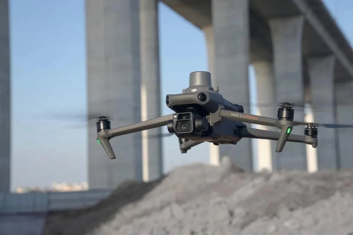
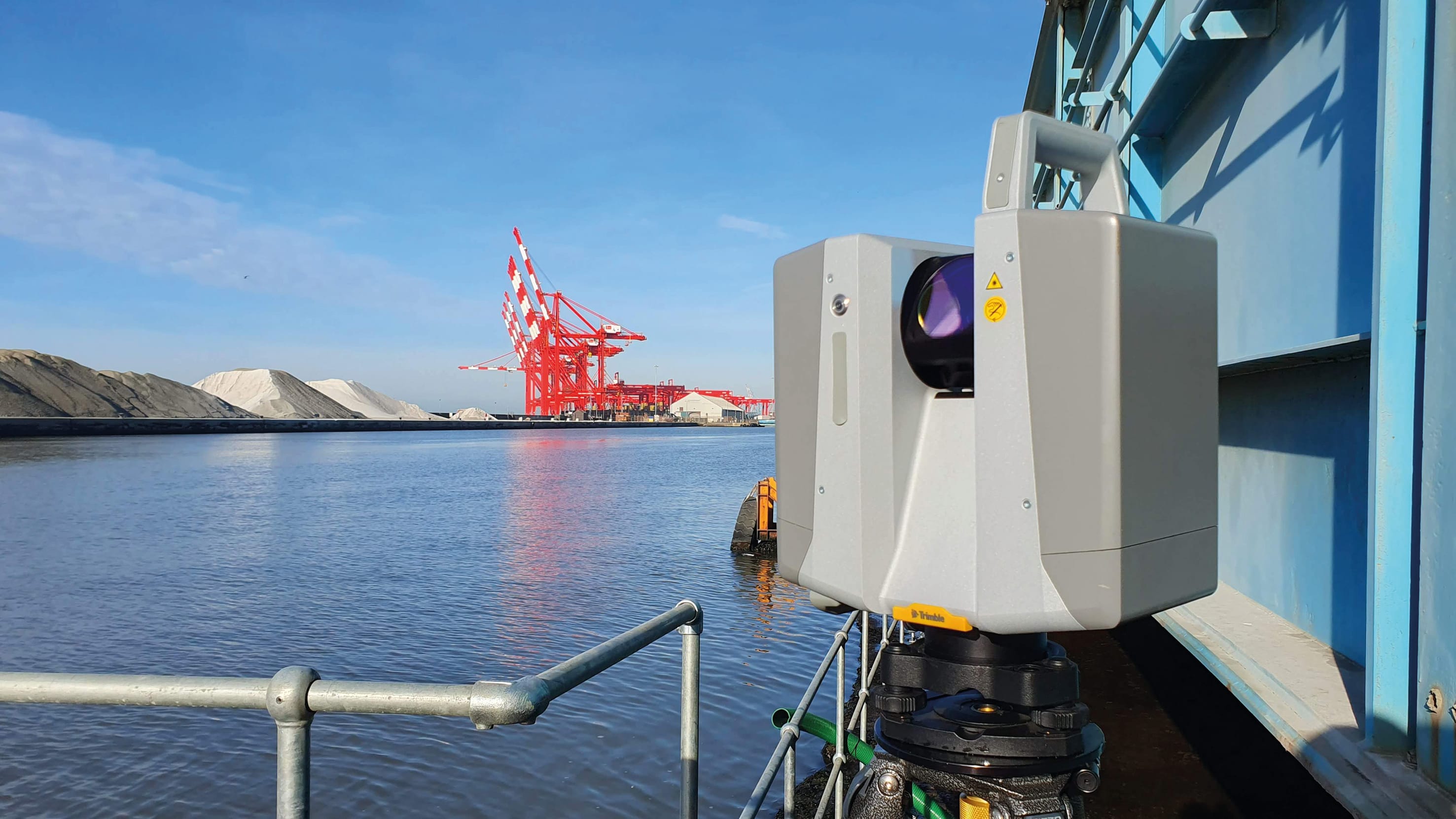
Equipment: Combination of terrestrial scanning (Trimble X12 for interiors) + drone LiDAR (DJI M4E + L3 for exterior and roof)
Indoor Arenas (10,000-20,000 Seats)
Arenas have more concentrated infrastructure:
- Ceiling catwalk and rigging systems for overhead cameras
- Scoreboard and lighting positions that create both obstructions and mounting opportunities
- Court-level positions with proximity to athletes (affects lens selection)
- Loading dock and back-of-house areas for compound placement
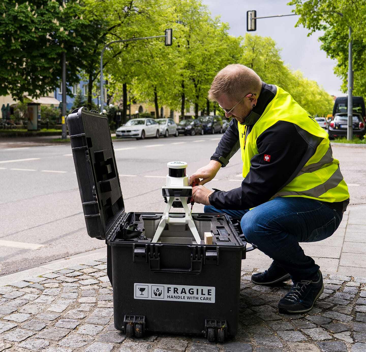
Equipment: Terrestrial scanning (FARO Focus Premium for ceiling detail) + mobile mapping (NavVis VLX3 for concourse areas)
Outdoor Courses (Golf, Rowing, Cycling)
Linear venues require different scanning approaches:
- Drone photogrammetry for complete course documentation
- Terrestrial scanning at key infrastructure points (grandstands, finish areas, commentary positions)
- GPS-referenced cable routing along course perimeters
Equipment: Drone photogrammetry (DJI M4E + P1) for course documentation + terrestrial scanning at infrastructure locations
Cable Routing and Infrastructure Planning
Cable routing is the most labor-intensive element of broadcast installation and the area where 3D scanning provides the greatest practical benefit.
The Scale of the Problem
A typical NFL broadcast involves 15-30 miles of cable. A Super Bowl or World Cup match may use 50+ miles. Each cable segment must be:
- Measured for exact length (cable is expensive — over-ordering wastes money, under-ordering delays installation)
- Routed through the venue without blocking exits, damaging finishes, or creating trip hazards
- Protected from weather, foot traffic, and vehicle traffic
- Labeled and documented for troubleshooting during the live event
How 3D Data Helps
The scan data enables:
- Exact cable length calculation: Routing through the 3D model along the actual path — including vertical runs, horizontal offsets, and service loops — gives accurate cable length specifications
- Conduit mapping: The scan captures existing conduit, cable trays, and raceways that can be reused for broadcast cable routing
- Clearance verification: The 3D model verifies that cable routes maintain required clearances from emergency exits, spectator areas, and structural elements
- Multi-event optimization: For venues that host multiple broadcasts per season, the 3D model supports optimization of permanent infrastructure (pre-installed conduit and junction boxes) that reduces setup time for each event
Temporary vs Permanent Broadcast Infrastructure
Temporary Infrastructure
Most broadcast installations are temporary — built for a single event or event series:
- Camera platforms and towers
- Commentary booths and interview positions
- Broadcast compound structures
- Cable runs and connection panels
The 3D model ensures that temporary infrastructure fits the venue without conflicting with existing structures or operations.
Permanent Infrastructure
Venues that regularly host broadcasts increasingly invest in permanent broadcast infrastructure:
- Pre-installed camera mounting positions at optimal sightline locations
- Permanent conduit and fiber optic backbone connecting camera positions to a dedicated broadcast room
- Built-in power distribution for camera and lighting equipment
- Permanent commentary booth positions with sightline-optimized seating
The initial 3D scan documents the venue as-built. When permanent broadcast infrastructure is added, a follow-up scan captures the modifications for ongoing documentation and future planning.
Working with Production Companies: Deliverable Requirements
Production companies need specific deliverable formats:
| Deliverable | Format | Use |
|---|---|---|
| Point cloud | E57, RCP | Engineering reference, measurements |
| 3D model (simplified) | SketchUp, FBX | Virtual walkthroughs, presentations |
| Floor plans | DWG, PDF | Cable routing, compound layout |
| Sections and elevations | DWG, PDF | Camera mounting detail, sightlines |
| Orthomosaic (aerial) | GeoTIFF | Site planning, compound placement |
| Virtual walkthrough | Web viewer, MP4 | Client presentations, remote review |
The most common request is a combination of point cloud (for engineering use) and simplified 3D model (for design visualization). Production designers work iteratively, placing and adjusting camera positions in the 3D model through multiple design cycles before finalizing the broadcast plan.
Frequently Asked Questions
How far in advance do production companies need venue scans? For major events (Super Bowl, Olympics, World Cup), scanning begins 12-18 months before the event. For regular-season broadcasts, scanning is typically done during the off-season before the first event of the year.
Can one scan serve multiple productions? Yes. A comprehensive venue scan serves all productions for that season. The scan data is reused for each event, with only modifications (temporary structures, seating configuration changes) requiring update scans.
What accuracy is needed for broadcast planning? Camera mounting and sightline planning requires ±10-20mm accuracy. Cable routing requires ±50mm accuracy. These requirements are comfortably met by standard terrestrial laser scanning.
Do you scan during events or between events? Primary scanning is done between events when the venue is empty. If event-specific documentation is needed (temporary structure positions, active lighting configuration), targeted scans can be performed during setup periods.
Learn more about our sports broadcast venue scanning services, stadium scanning capabilities, and digital twin solutions. Ready to discuss a venue scanning project? Request a quote.
Ready to Start Your Project?
Get a free quote and consultation from our 3D scanning experts.
Get Your Free Quote