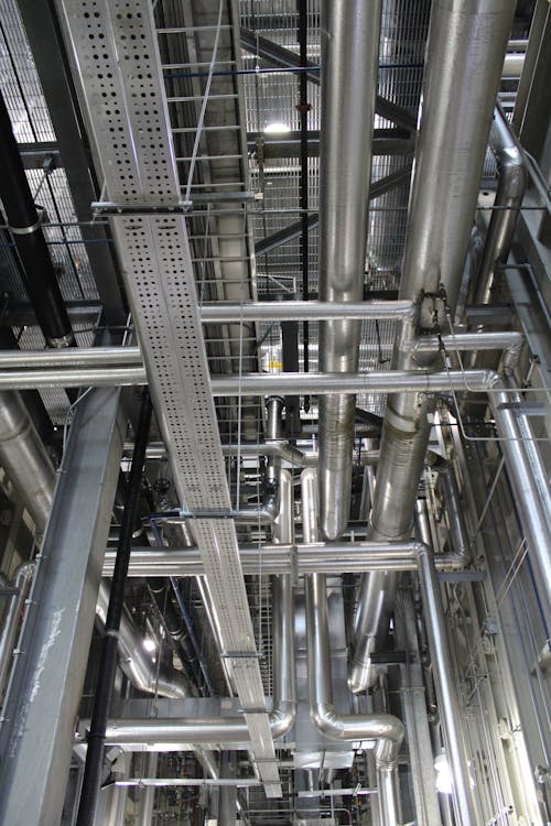
Behind every finished wall and above every drop ceiling, a building’s mechanical, electrical, and plumbing systems form a dense, interlocking network that keeps the structure functional. Ductwork routes air conditioning through tight ceiling plenums. Electrical conduit carries power from panels to outlets across multiple floors. Plumbing risers distribute water vertically while drain lines slope through horizontal chases at precise grades. Fire suppression piping threads between all of it.
These MEP systems represent 40 to 60 percent of a commercial building’s construction cost — yet they are the most frequently undocumented component of any existing structure. When the drywall goes up and the ceiling tiles snap into place, the physical evidence of what was actually installed disappears from view. And too often, the documentation disappears with it.
Why MEP Systems Are the Most Critical As-Built Component
Architectural elements are visible. You can measure a wall, identify a door swing, or verify a column location just by walking through the space. But MEP systems operate almost entirely out of sight, routed through ceiling plenums, wall cavities, floor chases, and underground trenches. Without documentation, the only way to know what is behind a wall is to open it.
This invisible complexity makes MEP documentation disproportionately valuable compared to architectural as-builts. A missing wall dimension delays work by hours. A missing pipe location can delay work by weeks — and cost tens of thousands of dollars in emergency rerouting.
The problem compounds in older buildings. Every tenant improvement adds electrical circuits. Every HVAC upgrade modifies ductwork routing. Every plumbing repair may reroute piping. After 20 or 30 years of modifications, the original mechanical drawings — if they still exist — bear almost no resemblance to what is actually installed.
The Hidden Cost of Missing MEP Documentation
When renovation design begins without accurate MEP as-builts, the design team is forced to make assumptions about what exists behind walls and above ceilings. Those assumptions create a predictable cascade of problems once construction begins.
Clash Detection Failures
The most expensive consequence is physical conflicts between new design and existing MEP infrastructure. A new HVAC duct routed through a ceiling plenum crashes into an existing electrical conduit run that nobody documented. A new plumbing line intersects with structural steel that was never shown on drawings. Each clash discovered during construction triggers a change order.
Industry data consistently shows that MEP-related change orders on renovation projects range from $50,000 to $150,000 for mid-size commercial buildings — and can exceed $500,000 on complex institutional projects. These costs are almost entirely preventable with accurate pre-renovation MEP documentation.
Coordination Delays
Even when clashes do not cause physical damage, the coordination delays are substantial. Discovering an undocumented 24-inch duct where the architect planned a new partition wall stops work until the design team can revise the layout. The mechanical subcontractor waits. The electrical subcontractor waits. The general contractor submits delay claims. Schedule overruns on renovation projects frequently trace back to undocumented MEP conditions.
Safety Incidents
Cutting into a wall or ceiling without knowing what is behind it creates genuine safety risks. Severed electrical lines, damaged gas piping, and breached pressurized water lines have all resulted from inadequate existing-conditions documentation. Beyond the immediate hazard, these incidents trigger work stoppages, incident investigations, and potential OSHA involvement.
What MEP As-Built Documentation Includes
Comprehensive MEP as-built documentation captures every system that keeps a building operational. The level of detail varies by project requirements, but a thorough MEP as-built package typically covers the following systems.
Mechanical (HVAC) Systems
- Air handling unit locations, sizes, and capacities
- Supply and return ductwork routing with dimensions and elevations
- Variable air volume (VAV) box locations and zones served
- Exhaust fan locations and duct routing
- Refrigerant line routing for split systems
- Chilled water and hot water piping (sizes, routing, valve locations)
- Thermostat and sensor locations with zone assignments
- Equipment access clearances and maintenance space requirements
Electrical Systems
- Electrical panel locations with circuit directories
- Conduit routing (sizes, types, and pathways)
- Transformer locations and capacities
- Bus duct and cable tray routing
- Generator and transfer switch locations
- Emergency and life safety circuit routing
- Data and telecommunications pathways
- Lighting fixture locations and circuiting
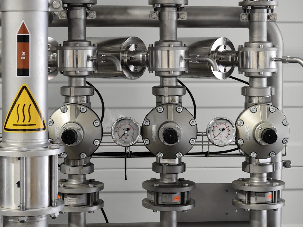
Plumbing Systems
- Domestic water supply piping (hot, cold, recirculated) with sizes and materials
- Sanitary drain, waste, and vent piping with sizes, materials, and invert elevations
- Storm drainage piping and roof drain locations
- Gas piping routing with valve locations
- Backflow preventer and pressure regulator locations
- Water heater and booster pump locations
- Fixture counts and types by floor
- Clean-out and access point locations
Fire Protection Systems
- Sprinkler main routing and riser locations
- Sprinkler head locations, types, and coverage areas
- Fire alarm panel locations and device wiring
- Standpipe locations and fire department connections
- Fire damper locations in ductwork
How 3D Laser Scanning Captures MEP Systems
Traditional manual measurement of MEP systems is extraordinarily time-consuming and error-prone. Reaching above ceilings with tape measures, sketching duct routing freehand, and estimating pipe elevations with a laser distance meter produces documentation that is incomplete at best and dangerously inaccurate at worst.
3D laser scanning fundamentally changes how MEP documentation is captured. A laser scanner placed in a mechanical room, ceiling plenum, or utility corridor captures every visible surface at millimeter-level accuracy — pipes, ducts, conduit, hangers, equipment, and structural elements alike. The resulting point cloud preserves the exact three-dimensional geometry of every component in its actual installed position.
The Progressive Scanning Approach
The most effective strategy for MEP documentation involves scanning at multiple stages of building access.
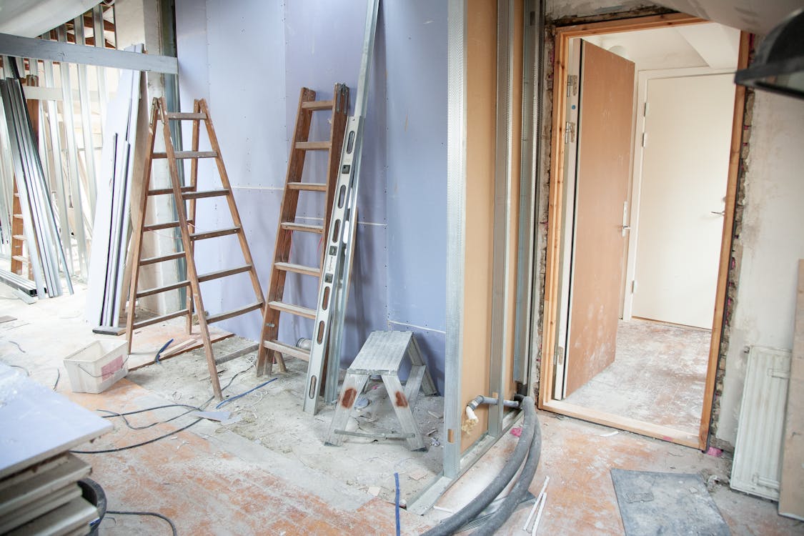
During selective demolition: When ceiling tiles are removed, walls are opened, or floors are cut for renovation, the exposed MEP systems should be scanned immediately — before new work covers them again. This window of access is often brief, sometimes just days, and capturing the data during this period eliminates the need for expensive exploratory demolition later.
Before drywall installation (new construction): For new construction projects, scanning MEP systems before walls and ceilings are closed creates an indisputable record of what was actually installed versus what was designed. This documentation is invaluable for the building owner during future renovations.
In accessible areas: Mechanical rooms, electrical rooms, ceiling plenums with removable tiles, and utility tunnels can be scanned without any demolition. These areas often contain the highest concentration of MEP systems and the most complex routing.
From Point Cloud to MEP Documentation

The raw point cloud data captures the geometry of every visible MEP component. From this data, our team delivers BIM-conversion-ready 3D laser scan data in industry-standard formats (E57, RCP, LAS) that allows your design team or BIM modeling firm to extract precise MEP routing, sizes, and spatial relationships.
Pipe diameters can be measured from the point cloud. Duct dimensions and routing can be traced. Conduit pathways can be mapped. Equipment clearances can be verified. All of this information comes from the scan data itself — no return visits to the site, no additional measurements needed.
Industry Standards for MEP Documentation
MEP as-built documentation quality is typically defined by Level of Detail (LOD) specifications, which describe how much information is captured and represented.
- LOD 200 — Approximate geometry. MEP elements are shown with approximate sizes, shapes, and locations. Suitable for general space planning and feasibility studies.
- LOD 300 — Accurate geometry. MEP elements are shown with precise dimensions, locations, and routing. Suitable for renovation design and coordination. This is the most commonly requested level for MEP as-built documentation.
- LOD 350 — Accurate geometry with coordination data. Includes hanger locations, support connections, and interfaces between systems. Required for detailed clash detection.
Our scanning data supports all of these LOD levels. The point cloud captures the physical reality at millimeter accuracy, providing the foundation that a BIM modeling firm needs to produce the required level of detail.
Real-World Scenarios Where MEP As-Builts Matter

Commercial Office Renovation
A property owner plans a full-floor tenant improvement in a 1990s office building. The original MEP drawings show the base building configuration, but three previous tenants made modifications that were never fully documented. Without MEP as-builts, the architect designs the new layout based on incomplete information. During demolition, the contractor discovers an undocumented 8-inch chilled water main running through the space where a new conference room was planned. Rerouting it costs $85,000 and delays the project by three weeks.
With pre-renovation MEP scanning, the design team would have identified that chilled water main during the design phase and routed the conference room accordingly — at zero additional cost.
Hospital System Replacement
A hospital needs to replace aging air handling units on three floors. The original mechanical drawings from 1985 do not reflect 40 years of modifications. Without scanning, the mechanical contractor spends two weeks tracing ductwork manually, accessing ceiling plenums throughout occupied patient floors. The incomplete manual survey misses a conflict between the new duct routing and an existing medical gas line, discovered during installation.
MEP scanning captures the entire ceiling plenum in a fraction of the time, with every component documented at its actual installed position. The conflict is identified during design coordination, not during construction over occupied patient areas.
Industrial Facility Equipment Installation
A manufacturing facility needs to install new production equipment that requires significant utility connections — compressed air, process water, electrical power, and data. The facility has been in operation for 25 years, and the utility routing above the production floor bears no resemblance to any existing drawing. Without documentation, the installation contractor cannot plan utility routing until equipment arrives and connections are attempted in the field.
Scanning the facility’s overhead utility systems creates a complete spatial record that allows the installation team to pre-plan every connection, pre-fabricate piping and conduit runs, and execute the installation with minimal production downtime.
Getting Started with MEP As-Built Documentation
Whether you are planning a renovation, upgrading building systems, or simply want a reliable record of what your building contains, MEP as-built documentation starts with a conversation about scope. The critical questions are:
- Which MEP systems need documentation? (All systems, or specific disciplines?)
- What areas of the building are accessible without demolition?
- Is selective demolition planned that would expose hidden systems?
- What deliverable formats does your design team or facility management system require?
- What level of detail is needed for your project?
Our team at THE FUTURE 3D specializes in capturing complex MEP environments with 3D laser scanning technology that documents every visible component at millimeter accuracy. We deliver BIM-conversion-ready scan data that your team can use directly for coordination, design, and facility management.
For projects where MEP documentation is part of a larger renovation effort, our comprehensive as-built documentation service covers architectural, structural, and MEP systems in a single coordinated scanning effort. Learn more about what as-built documentation costs in our pricing guide.
Ready to document your building’s hidden systems? Request a quote and our team will scope the right approach for your project.
Frequently Asked Questions
Q: Can 3D scanning capture MEP systems behind closed walls?
No — 3D laser scanning captures visible surfaces only. It cannot see through drywall, concrete, or other solid materials. For concealed MEP systems, scanning should be performed during selective demolition when systems are exposed, or before drywall is installed during new construction. In existing buildings with drop ceilings, scanners can capture above-ceiling MEP systems by removing ceiling tiles to provide line-of-sight access.
Q: How accurate is 3D scanning for measuring pipe and duct sizes?
3D laser scanning achieves accuracy of 1 to 4 millimeters at typical indoor scanning distances. Pipe diameters, duct dimensions, and equipment sizes can be measured directly from the point cloud data with high reliability. For nameplate data — such as equipment model numbers, electrical panel schedules, or valve tag numbers — traditional field verification is still needed alongside scanning, since these details are too small for laser scanners to resolve.
Q: What is the difference between MEP as-built drawings and MEP coordination drawings?
MEP as-built drawings document existing conditions — what is actually installed in the building today. MEP coordination drawings are produced during new construction to coordinate the routing of mechanical, electrical, and plumbing systems before they are installed. Both serve critical purposes, but as-built drawings reflect measured reality while coordination drawings reflect design intent.
Q: How long does it take to scan MEP systems in a typical commercial building?
For a single floor of a 20,000 to 50,000 square foot commercial building with accessible ceiling plenums, MEP scanning typically takes one to two days of on-site work. Mechanical rooms and electrical rooms with dense infrastructure may require additional scan positions. The total time depends on building complexity, accessibility of MEP systems, and the number of areas requiring ceiling tile removal for access.
Q: Should I scan MEP systems before or during renovation?
Both, if possible. Scanning before renovation captures the baseline existing conditions and allows the design team to identify conflicts early. Scanning during selective demolition captures systems that were concealed behind walls and above permanent ceilings — information that was not available during the pre-renovation scan. The combination of both phases produces the most complete MEP documentation.
Q: What file formats are MEP scan data delivered in?
We deliver point cloud data in industry-standard formats including E57 (universal format compatible with virtually all 3D software), RCP/RCS (for the Autodesk ecosystem including Revit and AutoCAD), and LAS/LAZ (for surveying and geospatial applications). Your design team or BIM modeling firm can import this data directly into their software to extract MEP information and produce coordinated drawings or BIM models.
Q: How much does MEP as-built scanning cost?
MEP scanning costs depend on building size, system complexity, and accessibility. For commercial projects, 3D scanning typically ranges from $3,000 to $15,000 depending on scope. Buildings with easily accessible ceiling plenums cost less than those requiring extensive ceiling tile removal or coordination with active operations. Contact us for a project-specific quote based on your building’s characteristics.
Ready to create accurate MEP as-built documentation for your building? Get a quote from THE FUTURE 3D or learn more about our as-built documentation services and 3D laser scanning capabilities.
Ready to Start Your Project?
Get a free quote and consultation from our 3D scanning experts.
Get Your Free Quote