3D laser scanning captures buildings and infrastructure with remarkable accuracy — millimeter-level precision across millions of measured points. But it is not magic, and it does not capture everything. Understanding the real limitations of the technology helps you plan better projects, set realistic expectations, and work with your scanning provider to get the most complete data possible.
This guide covers every significant limitation of 3D laser scanning, explains the physics behind each one, and provides the practical mitigation strategies that professional scanning teams use in the field.
Limitation #1: Line-of-Sight Requirement
This is the most fundamental constraint of laser scanning. The scanner can only measure surfaces that the laser beam can reach directly. If a surface is hidden behind another object — behind a wall, above a ceiling, inside a pipe, or below the floor — it simply does not exist in the scan data.
What This Means in Practice
- Behind-wall construction (framing, insulation, MEP in wall cavities) is invisible to the scanner
- Above-ceiling spaces (plenum, interstitial areas) are only captured if ceiling tiles are removed to expose the structure
- Below-floor systems (under-slab MEP, foundations) cannot be scanned unless the floor is opened
- Occluded surfaces (the back side of a column, the area behind a large piece of equipment) require additional scan positions from different angles
Mitigation Strategies
- Access all spaces — Open ceiling tiles in critical areas to expose MEP routing and structural connections. Remove access panels on equipment. Open electrical panels (when safe and with proper coordination)
- Multiple scan positions — For complex areas with many obstructions, add scan positions from different angles to capture surfaces that are hidden from other viewpoints. Professional scanning teams routinely add 20-30% more positions than the theoretical minimum to ensure coverage around obstructions
- Supplemental investigation — For truly concealed conditions (inside walls, below slabs), combine scanning with traditional investigation methods: borescope inspection, ground-penetrating radar, or selective demolition
- Document the gaps — Professional scanning teams note in their deliverables which areas could not be captured and why. This prevents downstream users from assuming that a gap in the point cloud means nothing is there
Limitation #2: Reflective and Transparent Surfaces
Laser scanners work by measuring the time it takes for a laser pulse to travel to a surface and bounce back. This process breaks down when the surface behaves unpredictably — reflecting the beam away at an angle instead of back to the scanner, or allowing the beam to pass through entirely.

Problematic Surfaces
- Glass — The laser passes through windows, glass partitions, and glass doors. These surfaces may appear as gaps in the point cloud, or the scanner may measure whatever is on the other side of the glass
- Mirrors — Create phantom points where the scanner “sees” a virtual copy of the room reflected in the mirror surface
- Polished metal — Stainless steel, chrome fixtures, polished aluminum, and glossy painted metal deflect the laser beam, creating either gaps or scattered noise points
- Standing water — Acts as a mirror for the laser, creating phantom reflections below the actual water surface
- Wet surfaces — Partially reflect the laser speculularly (like a mirror) rather than diffusely (scattering back to the scanner), reducing point quality
Mitigation Strategies
- Temporary matte coating — Apply removable scanning spray or powder to highly reflective surfaces before scanning. This creates a matte, diffusely reflective surface that the scanner can measure accurately. The spray removes cleanly after scanning
- Supplemental measurement — For glass surfaces, measure the glass position manually (tape or total station) and add those dimensions to the project record alongside the scan data
- Post-processing cleanup — Phantom points from mirrors and reflective surfaces are identifiable during processing and can be removed from the final point cloud
- Plan for it — When commissioning a scan in a building with extensive glass (curtain walls, glass partitions), understand upfront that the glass surfaces will not appear in the point cloud and plan supplemental documentation accordingly
Limitation #3: Very Dark and Light-Absorbing Surfaces
Laser scanning accuracy depends on receiving a return signal of sufficient strength. Very dark surfaces — matte black paint, dark rubber, dark carpeting, soot-covered surfaces — absorb most of the laser energy, returning only a weak signal with high noise.
What This Means in Practice
- Black-painted surfaces may have significantly more noise (scattered points) than lighter surfaces in the same scan
- Very dark surfaces at long range may not return enough signal to register any points at all
- Soot or carbon deposits (common in fire-damaged buildings) can cause large areas of missing data
Mitigation Strategies
- Scan closer — Reducing the distance between scanner and dark surface increases the return signal strength. Where possible, add scan positions specifically to reduce range to dark surfaces
- Increase quality settings — Most professional scanners allow the operator to increase the number of laser pulses averaged per point. More pulses = stronger signal = better data on dark surfaces, at the cost of longer scan time
- Accept reduced accuracy — In some cases, the data on very dark surfaces will be noisier than on lighter surfaces. For critical dimensions on dark surfaces, supplement the scan with manual measurements
- Matte spray on critical surfaces — If a dark surface is a critical measurement target (such as a dark structural steel member), temporary matte spray improves return signal quality
Limitation #4: Moving Objects
A single scan takes 1-3 minutes to complete its full 360-degree rotation. Anything that moves during that time creates artifacts in the point cloud — ghosting, streaking, or partially captured geometry.
Common Sources of Movement
- People walking through the scan — Creates “ghost” figures that are partially transparent and geometrically distorted
- Vehicle traffic in parking structures or outdoor areas
- Machinery in operation — Rotating equipment, moving conveyors, operating elevators
- Wind-affected objects — Trees, flags, tarps, loose materials
Mitigation Strategies
- Control access — For indoor scanning, brief occupants to avoid walking through the scanning area during active scans. A 2-minute pause is usually sufficient
- Schedule around activity — Scan parking structures early morning before traffic, mechanical rooms during equipment downtime, exterior areas during calm weather
- Post-processing removal — Moving objects captured from multiple scan positions can be filtered out during processing because they appear at different positions in overlapping scans, while the static geometry stays consistent
- Mark and document — If a moving object cannot be avoided (operating machinery that cannot be shut down), document it in the scan notes and plan for supplemental measurement if needed
Limitation #5: Hidden Elements (Behind Walls, Above Ceilings)
This is an extension of the line-of-sight limitation but deserves its own section because it is the most frequently misunderstood constraint. 3D scanning captures surfaces, not volumes. It cannot see through solid materials.
What Scanning Does NOT Capture
- Wall framing and insulation — Unless the wall is opened or partially demolished
- In-wall MEP routing — Electrical conduit, plumbing, and HVAC ductwork inside wall cavities
- Structural connections — How steel beams connect to columns or footings when those connections are concealed behind fireproofing, drywall, or cladding
- Foundation conditions — Below-slab construction, pile caps, grade beams
- Rebar layout — Inside concrete members unless exposed
Mitigation Strategies
- Remove ceiling tiles in renovation zones to expose above-ceiling conditions
- Open access panels and remove cover plates where accessible
- Use complementary technologies — Ground-penetrating radar for below-slab MEP, cover meters for rebar depth, borescope cameras for wall cavities
- Selective demolition — For critical renovation areas, coordinate with the demolition contractor to scan after selective demolition exposes hidden conditions
- Phase scanning with construction — For renovation projects, schedule scanning phases to capture conditions as they are exposed during the construction sequence
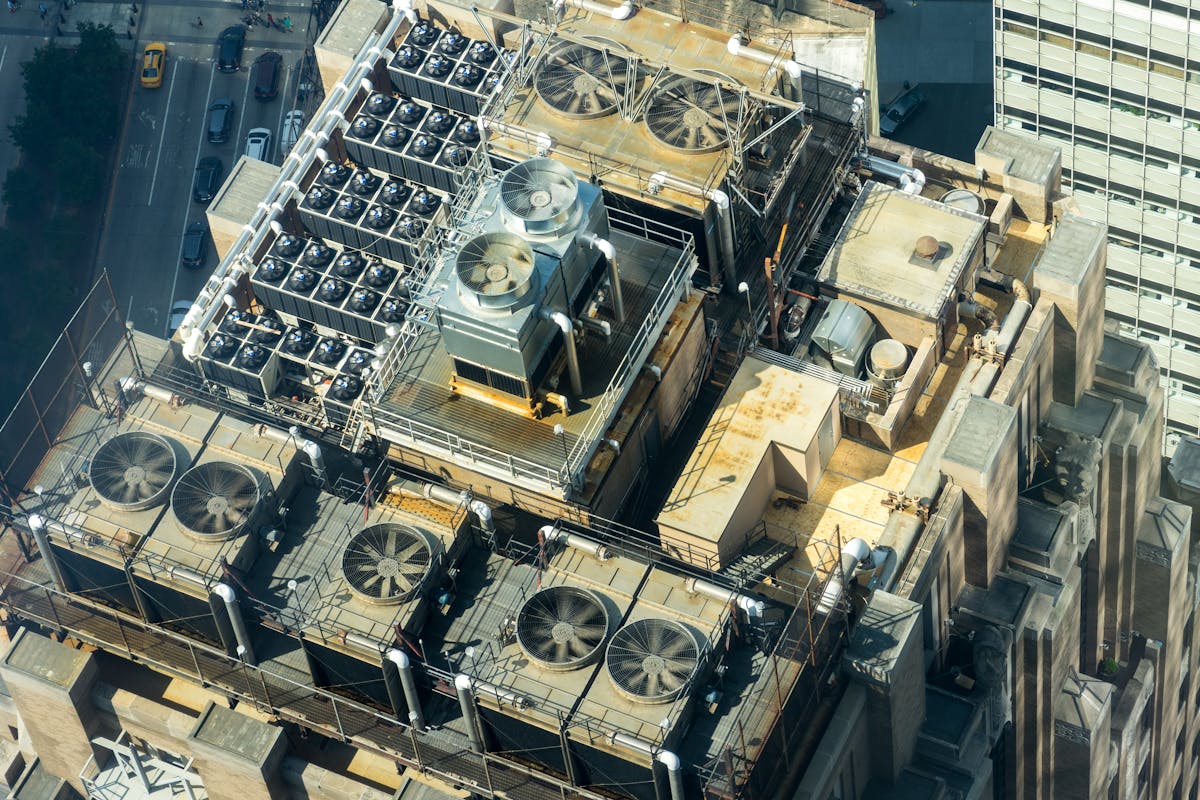
Limitation #6: Outdoor Range and Environmental Effects
While terrestrial laser scanners have ranges of 80-400 meters depending on the model, outdoor scanning introduces challenges that do not exist indoors.
Environmental Factors
- Rain — Water droplets scatter the laser beam, creating a dense cloud of noise points between the scanner and target surfaces. Light drizzle is manageable; moderate to heavy rain makes scanning impractical
- Fog and mist — Similar to rain, suspended water particles scatter the laser beam and reduce effective range
- Direct sunlight — On highly reflective surfaces (glass, water, polished metal), direct sunlight can saturate the scanner’s receiver, creating noise or phantom points
- Temperature extremes — Professional scanners operate within specified temperature ranges (typically -20 to 50 degrees C). Temperatures outside this range can affect accuracy and damage the instrument
- Wind — Does not directly affect the laser, but wind-induced vibration in the tripod degrades accuracy. Use wind shields or anti-vibration mounts in windy conditions
Mitigation Strategies
- Weather scheduling — Plan outdoor scanning for dry, overcast days (ideal conditions). Early morning and late afternoon avoid the worst effects of direct sunlight
- Use long-range equipment — The FARO Focus Premium series with up to 400-meter range is designed specifically for large outdoor scanning where longer reach reduces the number of required scan positions
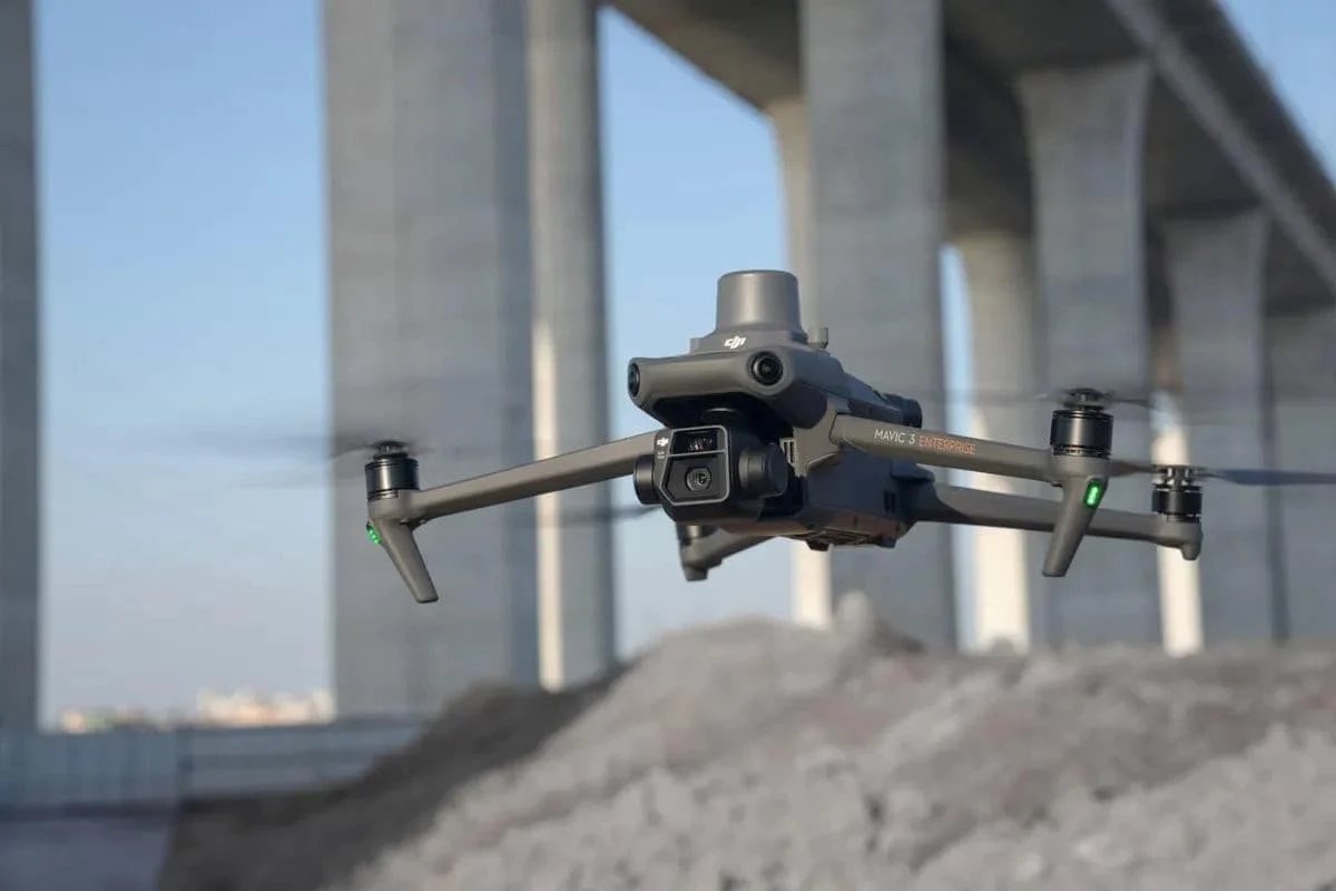
- Supplement with drone scanning — For large exterior areas, facades, and sites where terrestrial scanning is impractical, drone-based LiDAR and photogrammetry provide complementary coverage
- Accept weather-dependent rescheduling — Build weather contingency into outdoor scanning schedules. A one-day weather delay is cheaper than low-quality data from scanning in poor conditions
Limitation #7: File Size and Data Management
Professional point clouds are large. A single building scan with 150 positions at medium-to-high resolution generates 50-100 GB of raw data. A large industrial facility can produce terabytes of point cloud data.
Challenges This Creates
- Software performance — Loading and navigating a 50 GB point cloud requires capable hardware and optimized software. Standard office computers may struggle with large datasets
- Collaboration — Sharing point cloud files requires robust file transfer infrastructure. Email is not an option
- Long-term storage — Point cloud data should be retained as a permanent building record, which means long-term storage costs for large datasets
- BIM integration — Importing a full-building point cloud into Revit or other BIM software can be slow and memory-intensive. Most workflows use sub-sampled or sectioned point clouds for modeling
Mitigation Strategies
- Appropriate resolution — Scanning at the resolution needed for the project requirements, not at maximum resolution “just in case.” Medium resolution is sufficient for most AEC applications and produces files 3-5 times smaller than maximum resolution
- Cloud-based platforms — Use cloud-based point cloud viewers (Leica Cyclone Enterprise, NavVis IVION, Autodesk ReCap Cloud) that handle large datasets without requiring powerful local hardware
- Sectioned delivery — For large projects, deliver the point cloud in sections (by floor, by zone, by discipline) so that downstream users only load the data they need
- Optimized formats — Use format-specific optimization: RCS (Autodesk’s indexed format) loads much faster than raw E57 in Revit environments; LAS with LAZ compression reduces file sizes by 70-90% for archival storage
Limitation #8: Registration Drift in Large or Linear Spaces
When scanning long corridors, tunnels, or very large open spaces, registration accuracy can degrade progressively. Each scan-to-scan alignment introduces a small error, and these errors accumulate along the scan path.
Where This Matters Most
- Long corridors — A 500-foot hospital corridor scanned from one end to the other accumulates registration error with each scan position
- Tunnels and linear infrastructure — Underground utilities, transit tunnels, and pipeline corridors have the same cumulative error problem
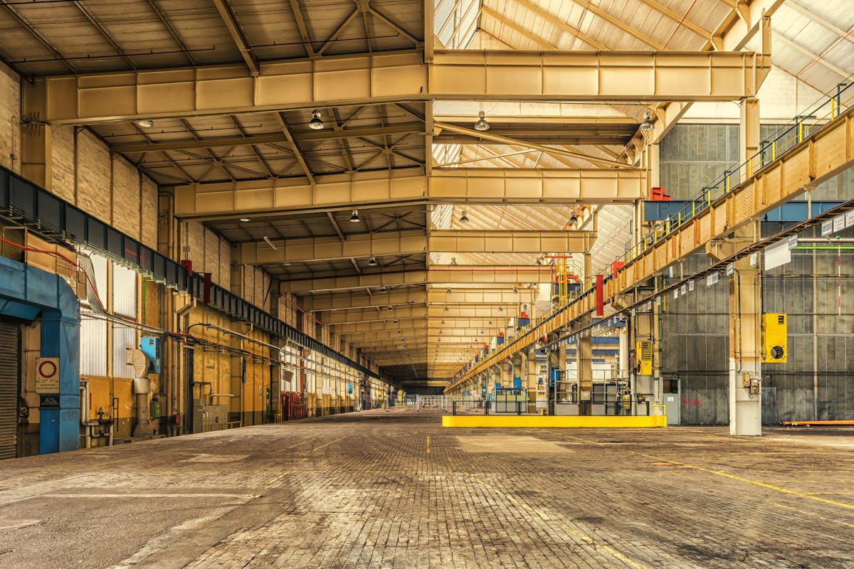
- Large single-story facilities — Warehouses, factories, and hangars where the scan path covers thousands of feet
Mitigation Strategies
- Loop closure — Plan scan routes that loop back to a starting point, allowing the registration software to distribute accumulated error evenly rather than concentrating it at one end
- Control points — Establish surveyed control points throughout large spaces and constrain the registration to match these known positions
- Target networks — Create a dense network of registration targets with strong geometric distribution (varying heights, multiple distances) to strengthen registration geometry
- Break into zones — Divide large facilities into manageable zones, register each zone independently to control points, then merge the zones in post-processing
The Honest Summary
3D laser scanning is the most accurate, comprehensive, and efficient method available for documenting existing physical conditions. But it operates within physical constraints that cannot be engineered away — the laser must reach the surface, the surface must return the laser, and the environment must allow the laser to travel cleanly.
Every limitation listed above has a known mitigation strategy. Professional scanning teams plan for these challenges before they arrive on site, and they use a combination of scanning technique, supplemental measurement, and post-processing to deliver the most complete data possible within the physics of the technology.
The key is communication. When you work with a scanning provider, discuss the specific conditions of your building — glass surfaces, dark paint, restricted access areas, active operations — so they can plan their approach accordingly. No scan covers 100% of every surface, but a well-planned scan captures everything that matters for your project.
Frequently Asked Questions
Can a laser scanner see through walls?
No. Laser scanning is a surface measurement technology — it captures the position and color of visible surfaces only. Concealed construction (framing, in-wall MEP, below-slab conditions) is not captured. For hidden conditions, complementary technologies like ground-penetrating radar, borescope inspection, or selective demolition are used alongside scanning.
What percentage of a building does a scan typically capture?
A well-executed scan of a building with standard access (all rooms accessible, ceiling tiles removed in key areas) typically captures 85-95% of all visible surfaces. The remaining 5-15% represents areas blocked by furniture, inside cabinets, behind permanent fixtures, and other minor obstructions that are generally not critical for most projects.
Does rain prevent scanning completely?
Light drizzle can be managed with reduced range settings and additional post-processing to filter noise. Moderate to heavy rain makes outdoor scanning impractical due to excessive noise from water droplet scattering. Indoor scanning is unaffected by weather. Professional scanning teams build weather contingency into outdoor project schedules.
How do you handle glass curtain walls?
Glass curtain walls are one of the most common challenging surfaces. The standard approach is to scan the building as-is (capturing the mullion framework and any opaque surfaces behind the glass), then supplement with manual measurements of the glass panel positions and sizes. For critical dimensional requirements, temporary matte spray can be applied to glass surfaces to make them visible to the scanner. The glass limitation is documented in the deliverables so downstream users understand the data coverage.
Understanding these limitations helps you plan better projects and get more value from your scanning investment. For a related perspective on what people often get wrong about the technology, see our article on 5 misconceptions about 3D scanning that cost you money. Get a quote from THE FUTURE 3D, or explore our guide on how 3D scanning works for a deeper understanding of the technology and its capabilities.
Ready to Start Your Project?
Get a free quote and consultation from our 3D scanning experts.
Get Your Free Quote